Intermittent Fault Detector™ (IFD-256™) Test Summary
Introduction:
Pratt & Whitney V2500-A5 Training Engine
S/N: V10045
The subject engine was tested by Universal Synaptics, Derco, and Pratt & Whitney technicians and personnel on 19-20 February 2019 using the Portable Intermittent Fault Detector™ (PIFD™). The Interface Test Adaptor (ITA) was designed and manufactured by Derco for this collaborative Technology Demonstration Project (TDP). This ITA connected to an estimated 75% of the engine harness connectors.
Test Procedures:
- AutoMap™ – discover the Unit Under Test (UUT) true as-wired configuration
- Continuity – test for open circuits and measure resistance against established AutoMap baseline (open circuits / high resistance tests)
- Shorts – provide shorts indication and shorts tracing
- Intermittence – monitor all circuits to detect and isolate all three Stages of intermittent faults (see Graphic 1)
- Fault Isolation – detect intermittent faults to root cause through programmatic isolation
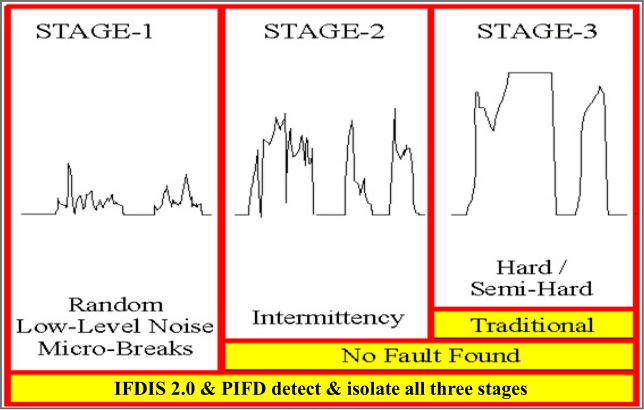
Graphic 1 – Three Stages of an Intermittent Fault
Stage 1 – random low-level nanosecond microbreaks, likely not operationally evident yet, but on curve of degradation to become Stage 2
Stage 2 – intermittent failure evident to pilot in operation, reported to ground crew, passes ground test and labeled No Trouble Found (NTF) or No Fault Found (NFF), on curve of degradation to become Stage 3
Stage 3 – semi-hard or hard failures, Automatic Test Equipment (ATE) and troubleshooting tools such as DMMs designed to detect hard faults (open circuits or shorted circuits)
Results:
Channel A:
- Continuity testing was conducted, and no open circuits were found in the engine.
- Shorts testing was conducted, and no shorted circuits were found in the engine.
- Intermittence testing was conducted, and one circuit experienced 12 intermittent events on Channel A.
- Location: Connector 4000KS, J3-H, Wire 77, Connected to Node 70 (Graphic 1 and Graphic 2)
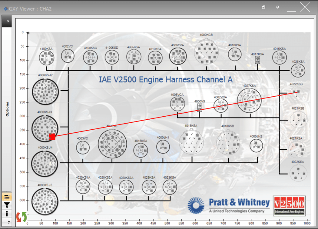
Graphic 1 – Fault Isolation Graphic – S/N: V10045 Engine Harness Channel A
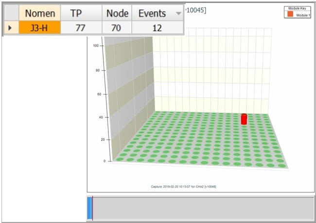
Graphic 2 – Intermittence Graphic – S/N: V10045 Engine Harness Channel A
-
- Root Cause Analysis: P&W engineer was able to diagnose the intermittent fault to root cause base on the Fault Isolation Graphic (Image 1 & 2)
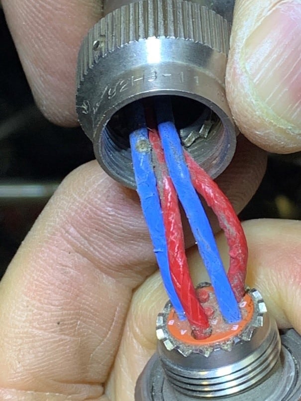
Image 1 – J3-H, Wire 77 Chaffing
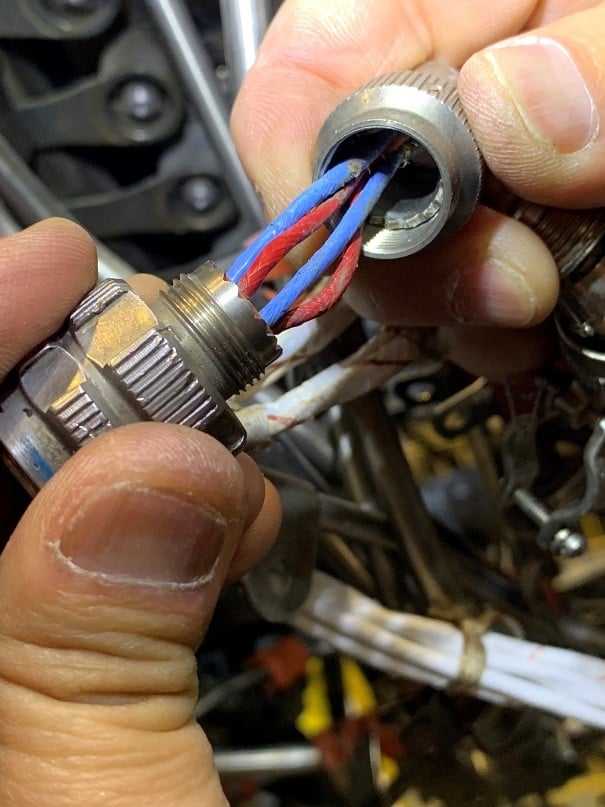
Image 2 – J3-H, Wire 77 Expose causing intermittent connectivity
Channel B:
- Continuity testing was conducted, and no open circuits were found in the engine.
- Shorts testing was conducted, and no shorted circuits were found in the engine.
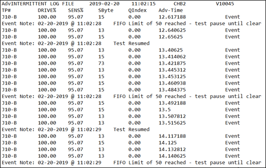
- Intermittence testing was conducted, and one circuit experienced 50+ intermittent events on Channel B.
- Location: J10-B, Wire 98, Connected to Node 215 (Graphic 3, screenshot taken at 20 events)
- Intermittence Log File (Report 1): Indicates Intermittence Test start time, location of fault (TP#), and time when intermittent fault occurred during test (Adv-Time). Report shows how the maintainer used the Voyager to reconfirm faults. Event or glitch limit was reached at user-selected 50 intermittent events or faults. Data indicates that the user cleared test results several times to reconfirm the trouble area on the harness through manual manipulation confirming intermittent fault on J10-B.
- Root Cause Analysis: P&W engineer was able to diagnose the intermittent fault to root cause based on the Fault Isolation Graphic (Image 3)
Report 1 – Intermittence Report – S/N: V10045 Engine Harness Channel B
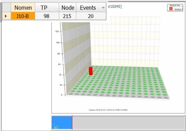
Graphic 3 – Intermittence Graphic – S/N: V10045 Engine Harness Channel B
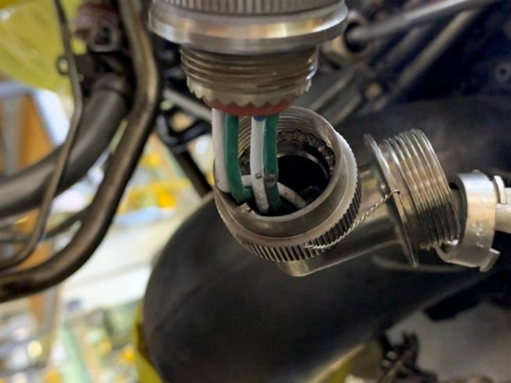
Image 3 – J10-B, Wire 98 Chaffin, exposed wire causing intermittent connectivity
S/N: V10024
The subject engine was tested by Universal Synaptics, Derco, and Pratt & Whitney technicians and personnel on 20 February 2019 using the portable Portable Intermittent Fault Detector™ (PIFD™). The Interface Test Adaptor (ITA) was designed and manufactured by Derco for this collaborative Technology Demonstration Project (TDP). This ITA connected to an estimated 75% of the engine harness connectors.
Test Procedures:
- AutoMap™ – discover the Unit Under Test (UUT) true as-wired configuration
- Continuity – test for open circuits and measure resistance against established AutoMap baseline (open circuits / high resistance tests)
- Shorts – provide shorts indication and shorts tracing
- Intermittence – monitor all circuits to detect and isolate all three Stages of intermittent faults (see Graphic 1)
- Fault Isolation – detect intermittent faults to root cause through programmatic isolation
Results:
Channel A:
- Continuity testing was conducted, and no open circuits were found in the engine.
- Shorts testing was conducted, and no shorted circuits were found in the engine.
- Intermittence testing was conducted, and Channel A is *certified intermittent free.
Channel B:
- Continuity testing was conducted, and no open circuits were found in the engine.
- Shorts testing was conducted, and no shorted circuits were found in the engine.
- Intermittence testing was conducted, and Channel B is *certified intermittent free.
*ITA connected to estimated 75% of engine harness connectors
