Portable Intermittent Fault Detector™ (PIFD-512™) Test Summary
F/A-18 EWIS Nose Landing Gear & Flight Control System Test Summary
Introduction
Universal Synaptics (USC) delivered Portable Intermittent Fault Detector™ (PIFD™) technology and Interface Test Adapters (ITA) to REDACTED at REDACTED Air Force Base from 7-11 February 2022. PIFD training was conducted during the same time period. PIFD testing, to include AutoMap™, Continuity, Shorts, and Intermittence tests, was performed on-site with REDACTED, REDACTED, and USC personnel to create finalized Test Program Set (TPS) maps for the Nose Landing Gear (NLG) and Flight Control System (FCS) Electrical Wiring Interconnection System (EWIS) subcomponents. Testing for continuity issues, shorts, and intermittent faults was also performed through on-job training on two F/A-18 aircraft.
REDACTED and REDACTED EWIS troubleshooting team members have leveraged conventional troubleshooting tools such as ohmmeters or digital multimeters to detect hard faults in EWIS. This process of “pinning out” an EWIS harness entails manual point to point connection of the test lead to the desired test point and closing the loop on the other end of the harness with the other test lead. This can be a very time intensive process and often leads to No Fault Found (NFF) test results due to the manual error prone nature of the process, but also due to the lack of sensitivity of this type of test and its inability to detect and isolate intermittent or transient faults that only manifest under environmental stress such as temperature and vibration. The goal of this technology delivery was to provide and streamline EWIS troubleshooting for the REDACTED F/A-18 aircraft through the deployment of automated technology, to include the detection and isolation of intermittent issues that are undetectable with traditional troubleshooting tools and standard troubleshooting processes.
The REDACTED F/A-18 weapon system experiences EWIS faults and intermittent issues. Past experiences of reported issues from REDACTED pilots have led technicians to specific EWIS or components following recommended fault trees, only to test NFF and be approved for flight with no diagnosed issue(s). The REDACTED and REDACTED team is capable of identifying hard faults leveraging handheld tools but has never had the technology to automate that process for speed and rapid testing nor the ability to detect and isolate intermittent faults that are the prime driver of NFF test results. These diagnostic processes are reactive in nature, meaning that faults are only identifiable after they become operationally evident. The delivery of PIFD technology allows REDACTED to better support the REDACTED through prognostic testing and allows for root cause identification of intermittent issues that traditional tools and functional bench tests are incapable of detecting.
The implementation of the PIFD into the REDACTED and REDACTED test process will reduce NFF test results, provide the ability to rapidly detect and isolate opens, shorts, and intermittent faults, and improve the readiness of the REDACTED F/A-18 fleet. Significant reductions in sell-off / qualification test time will also be achievable as intermittent-free assets will easily pass go/no-go, pass/fail validation tests that are required prior to installing or an EWIS or component on the weapon system.
The on-job training and testing conducted during this project demonstrated the advanced prognostic and diagnostic capability of the only approved US DoD MIL-PRF-32516 tester. The PIFD’s applicability to the NLG and FCS EWIS test procedures as well additional UUTs moving forward was also demonstrated. USC delivered a PIFD-512 with ITAs for the NLG and FCS subcomponents built with opposite gender mating connectors for those respective UUTs. Basic schematic data was provided by REDACTED and no Test Program Set (TPS) was developed prior to arrival, thus demonstrating the PIFD’s AutoMap™ capability.
Test Procedures
- AutoMap – discovered the as-wired configuration of 11 different EWIS UUTs (1 NLG map, 14 FCS maps) across two F/A-18 aircraft – Tail #REDACTED, and Tail #REDACTED
- UUTs were unable to be sent to USC as gold assets for baseline mapping. This necessitated a comparison of the AutoMap findings on Tail #REDACTED and Tail #REDACTED against the UUT schematics. The USC Technical Team was standing by to update the PIFD test database due to differences from the AutoMap findings and the provided schematics.
- Continuity – tested for open circuits and measured resistance against established AutoMap baseline (open circuits / high resistance tests)
- Shorts – provided shorts indication and shorts tracing
- Intermittence – monitored all circuits simultaneously and continuously to detect and isolate all Three Stages of an Intermittent Fault (Figure 1)
- Fault Isolation – detected intermittent faults through programmatic isolation
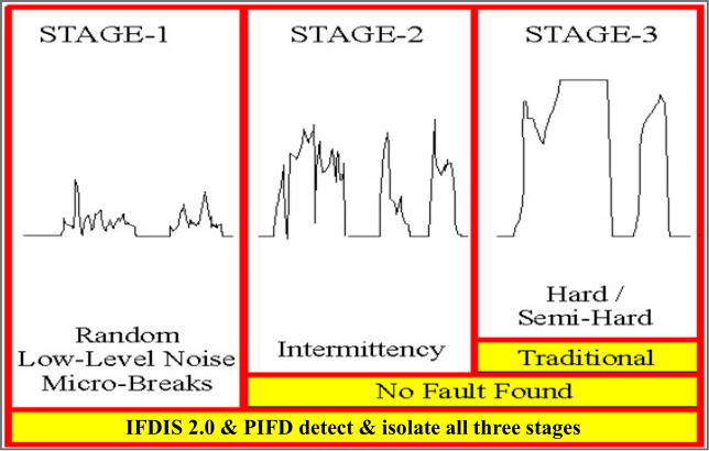
Figure 1 – Three Stages of an Intermittent Fault
Stage 1 – random low-level nanosecond microbreaks, likely not operationally evident yet, but on curve of degradation to become Stage 2
Stage 2 – intermittent failure evident to pilot in operation, reported to ground crew, passes ground test and labeled No Trouble Found (NTF) or No Fault Found (NFF), on curve of degradation to become Stage 3
Stage 3 – semi-hard or hard failures, Automatic Test Equipment (ATE) and troubleshooting tools such as DMMs designed to detect hard faults (open circuits or shorted circuits)
Connecting the Interface Test Adapter (ITA)
The ITAs delivered for this project to test the F/A-18 NLG and FCS subcomponents each had five (5) sub-assemblies with NLG ITA having five (5) D-sub connectors (Figure 2), marked J1-J5, and the FCS ITA having nine (9) D-sub connectors, marked JA-JH, and JJ. The D-sub connectors for NLG testing plug into the PIFD matching J1 to J1 through J5 to J5. The D-sub connectors for FCS sub-systems testing plug into the PIFD in accordance with Figure 4 – FCS Test Configurations.
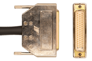
Figure 2 – 50 pin D-Sub
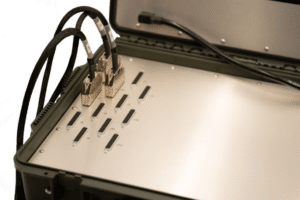
Figure 3 – D-Sub connected to PIFD
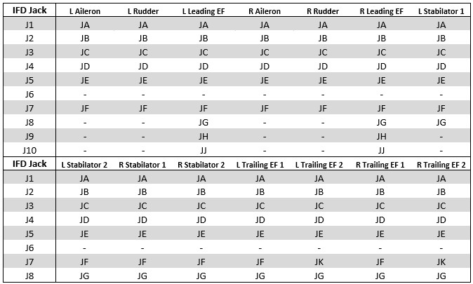
Figure 4 – FCS Test Configurations
The NLG ITA has 22 cannon connectors, each labeled to match the opposite gender mating connector of the UTT. These connectors are as follows:
- 52P-F058B
- 52P-F058E
- 52P-D092C
- 52P-D026A
- 12J-G060
- 12P-G005
- 12P-J029
- 52J-C051
- 84P-G035A
- 84P-G035B
- 12J-G061
- 34P-G003
- 7P-G026
- 10P-F015
- 52J-G040
- 52P-C057G
- 12P-E004A
- 52P-C057F
- 12P-H008
- 52P-H084
- 52P-K303A
- 76P-H009A
The FCS ITA has 15 cannon connectors, each labeled to match the opposite gender mating connector of the UUT in accordance with the desired subcomponent test, as outlined in Figure 5 – FCS Connector Configurations.
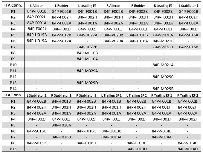
Figure 5 – FCS Connector Configurations
Test Plan and Procedures
- AutoMap™
- AutoMap™ was performed as follows to discover the as-wired configuration of the NLG and the FCS subcomponents. This was completed on Tail #REDACTED and Tail #REDACTED and the USC and REDACTED teams reviewed results and verified against available schematics.
- Login as Advanced Technician
- Select the appropriate map from the group
- Run Automap
- Log out of Advanced Technician
- AutoMap™ was performed as follows to discover the as-wired configuration of the NLG and the FCS subcomponents. This was completed on Tail #REDACTED and Tail #REDACTED and the USC and REDACTED teams reviewed results and verified against available schematics.
- Conventional Tests
- Continuity and shorts tests were performed while UUTs were in a static state to evaluate the UUTs. Operators and technicians were unable to repair any hard opens or shorts, pending REDACTED Over and Above repair approval. Conventional tests were performed as follows.
- Select appropriate map with the highest Rev or final version from Map Group
- Input Serial Number of the UUT and press Enter
- Press Start button to run Continuity and Shorts testing.
- Address any open or shorted circuits, as per local process.
- Continuity and shorts tests were performed while UUTs were in a static state to evaluate the UUTs. Operators and technicians were unable to repair any hard opens or shorts, pending REDACTED Over and Above repair approval. Conventional tests were performed as follows.
- Intermittence Testing
- Starts automatically if no open or shorted circuits are present in the UUT and differs from the scanning tests above as this test constantly monitors all electrical paths simultaneously and continuously. Testing period is technician determined to allow for environmental and/or vibrational profile or manual manipulation of the UUT. Intermittent events, displayed in real time with precision, will show in RED on the Fault Isolation Graphic as highlighted in Figure 6.
- Fault Isolation
- Performed Fault Isolation to begin to visually identify root cause(s) of the intermittent fault(s).
- Reports
- Detected and Isolated faults discovered during PIFD testing will be compiled and exported to the “Reports” folder on the PIFD Desktop.
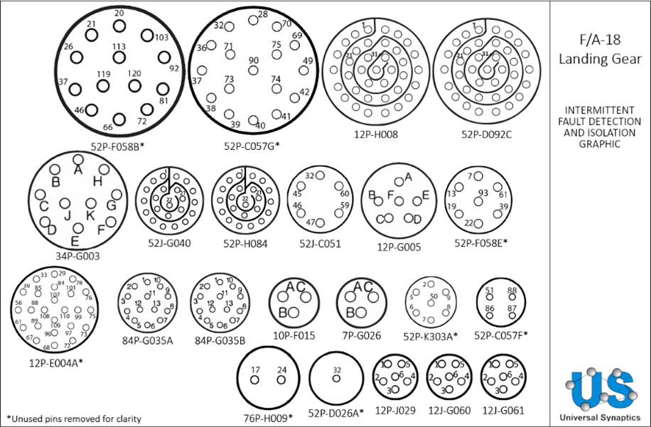
Figure 6 – NLG Fault Isolation Graphic
Results
- PIFD AutoMap executed on NLG and FCS EWIS UUTs – as-wired configuration of all UUTs discovered, on average, in less than five (5) minutes
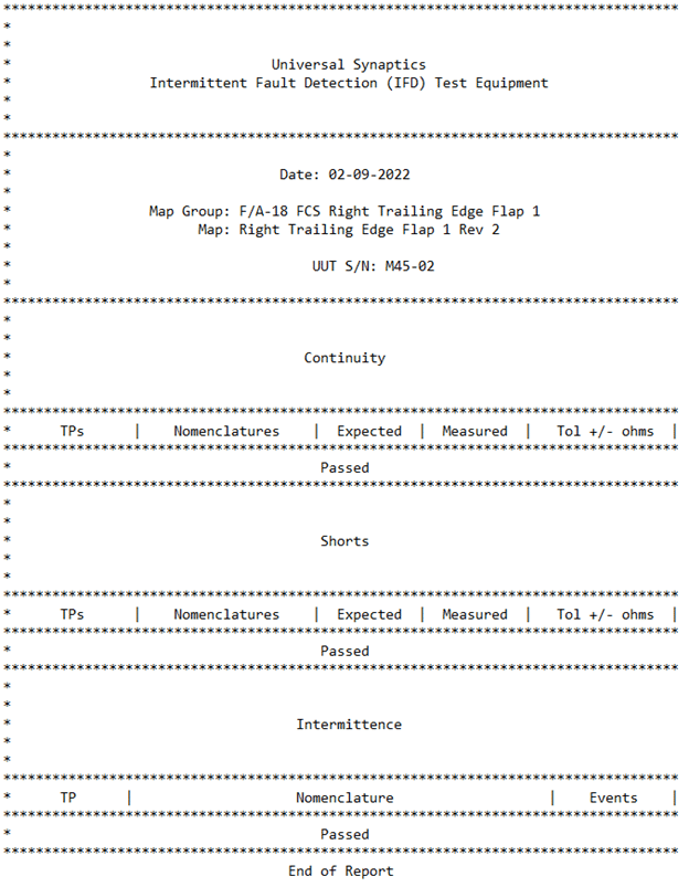
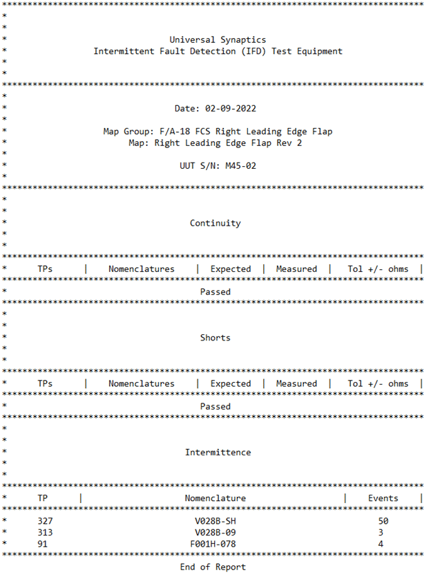
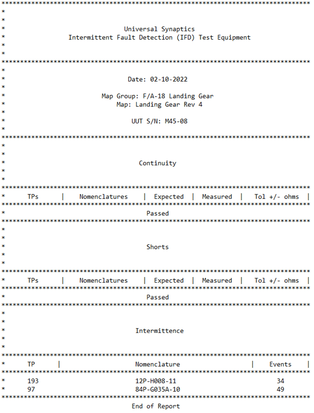
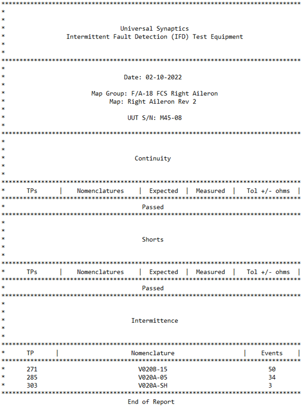
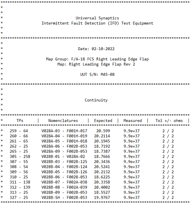
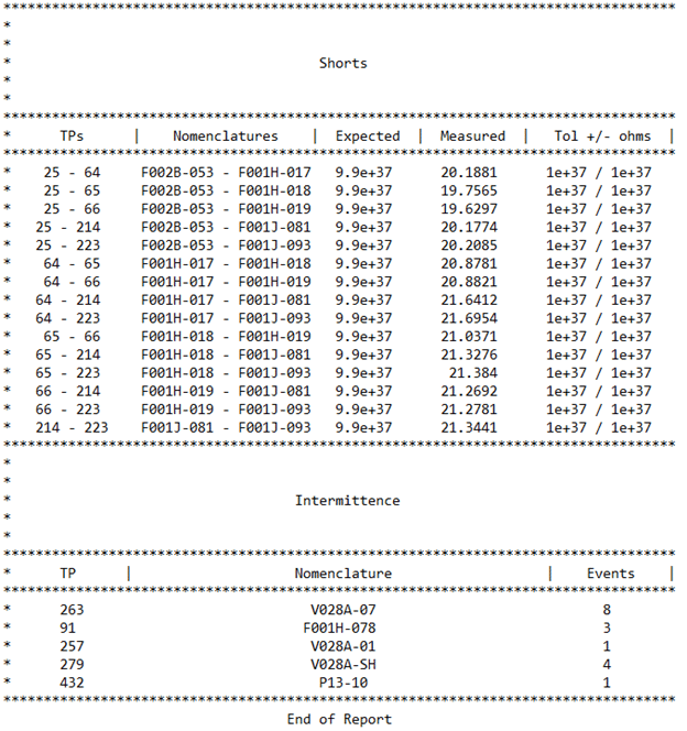
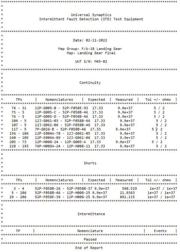
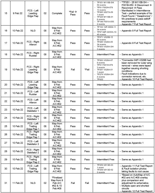
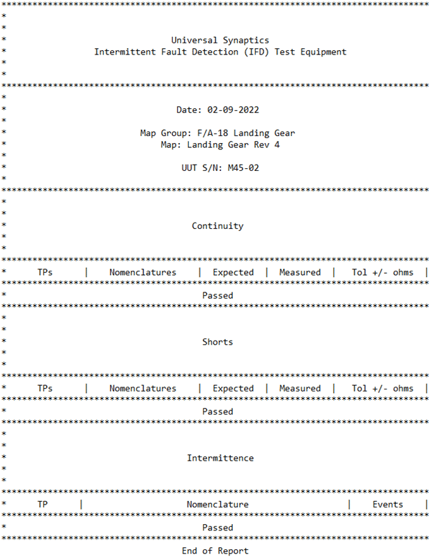
- PIFD Continuity testing conducted – see Table 1 for specific UUT test results
- PIFD Shorts testing conducted – see Table 1 for specific UUT test results
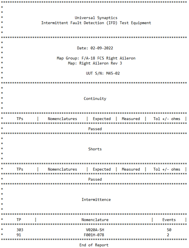
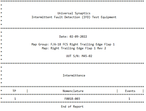
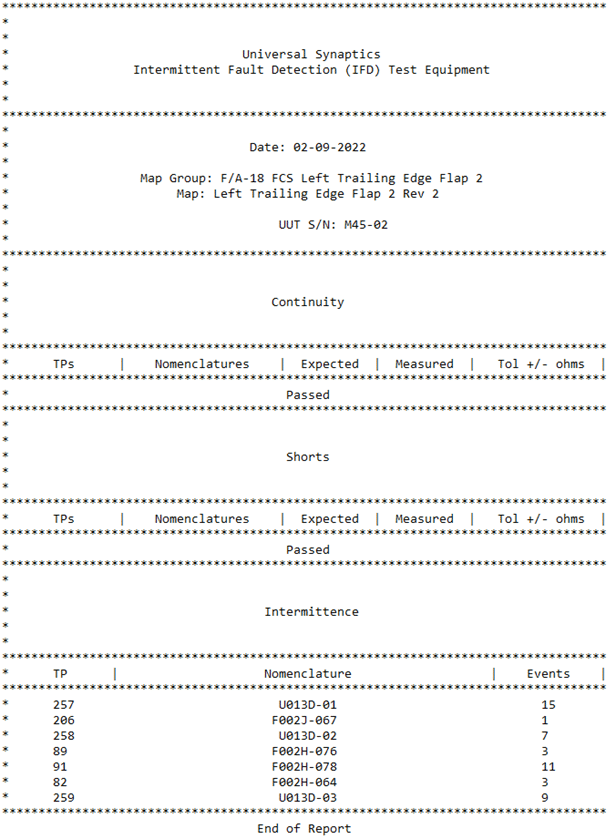
- PIFD Intermittence testing conducted – see Table 1 for specific UUT test results
- PIFD Fault Isolation – some intermittent faults were taken to root cause visually and will be highlighted below. The majority of intermittent issues were not taken to root cause due to required REDACTED approval for repairs. These faults were annotated and tagged appropriately to allow the REDACTED / REDACTED team to repair later and are highlighted in Table 1.
Table 1 – Test Results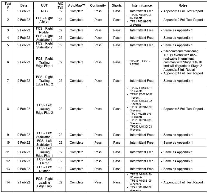
Lessons Learned
- The PIFD-512 and manufactured ITAs for NLG and FCS sub-systems provided adequate coverage of needed circuit connections to test according to the planned test procedures. The team discussed future expansion of PIFD testing to other EWIS and components. It was recommended that a simple ITA test and manufacturing approach be followed by trying to focus on smaller harness runs and not a combination of different cable harness being built into one ITA test capability. While this in not always feasible, based on different EWIS branching out to components or parts of the aircraft, it is highly recommended to simplify a test for ease of manufacturing, setup, test procedure, and root cause failure analysis.
- USC can continue to provide ITA manufacturing capability to REDACTED or USC can quote cost of training REDACTED in setting up this manufacturing process and capability as an IFD ITA Manufacturing Certified Facility – see www.usynaptics.com/ita.
- The test team utilized a simple handheld vibration tool to allow the intermittent issues to manifest as this failure mode only wreaks havoc on EWIS and systems with environmental stimulus. The vibration tool leveraged was a Theragun mini.
- The combined team from REDACTED / REDACTED / USC built quick rapport and worked efficiently to conduct on-job training and prepare REDACTED for continued use of the PIFD testing the NLG and the FCS subcomponents on the F/A-18 platform for REDACTED. Use of the PIFD across additional F/A-18 EWIS and smaller components is feasible and the REDACTED team is well-equipped and prepared to improve readiness on the Hornet fleet.
- The REDACTED PIFD test team can easily expand use of the technology to other platforms, such as the C-130, helicopters, and any others, leveraging AutoMap once ITAs are manufactured to connect the PIFD to the desired UUT.
- REDACTED will save numerous man hours by leveraging Continuity and Shorts hard fault testing provided by the PIFD. Previous process entails point-to-point use of an ohmmeter or digital multimeter. The PIFD greatly simplifies these Stage 3 tests and removes the potential for human error.
- Initial testing on Day 1 on Aircraft Tail #REDACTED experienced a delay in testing due to the PIFD experiencing significant noise in the hangar. Noise or chaos to the neural network can be caused by weather, different testers running in an adjacent room, and numerous other factors. After discussing the experience with the USC technical team that evening, the first course of action to resolution was to unhook the earth ground to the aircraft in the bay of the hangar where testing was conducted. This disconnect removed the noise and the tester functioned without issue, thus indicating an issue with the earth ground in that bay. The PIFD is a sensitive diagnostic instrument and has uncovered earth ground issues in hangar bays for the US Air Force and US Navy. It is recommended that this earth ground be tested according to local procedure. The other earth was connected with no issues to testing, indicating a good earth ground. This procedure was followed on Aircraft Tail #REDACTED the next day and that earth ground also caused chaos to the tester, indicating that it should be verified as well. USC has annotated these findings and is making considerations for addressing this issue via technical support guidance and/or visual indication on the test screen.
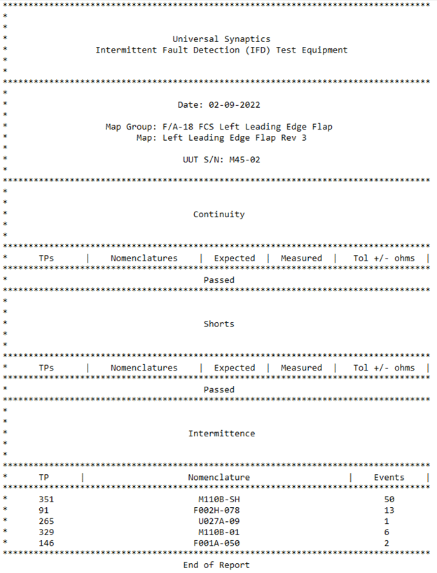
- In Table 1 – Test Results, Test #15 is highlighted and was conducted on the FCS – Left Leading Edge Flap on Tail #REDACTED. AutoMap was completed and then test commenced. Continuity immediately showed three (3) issues – one (1) circuit was now open (TP 351 – 25, M110B-SH – F001B-053) varying from the baseline AutoMap of 26.95ohms as discovered minutes before to Open or 9.9e+37 – see Figure 7 – Left Leading Edge Flap Continuity Results #1. The other two (2) issues simply were outside of the established default +/- 2ohm tolerance.
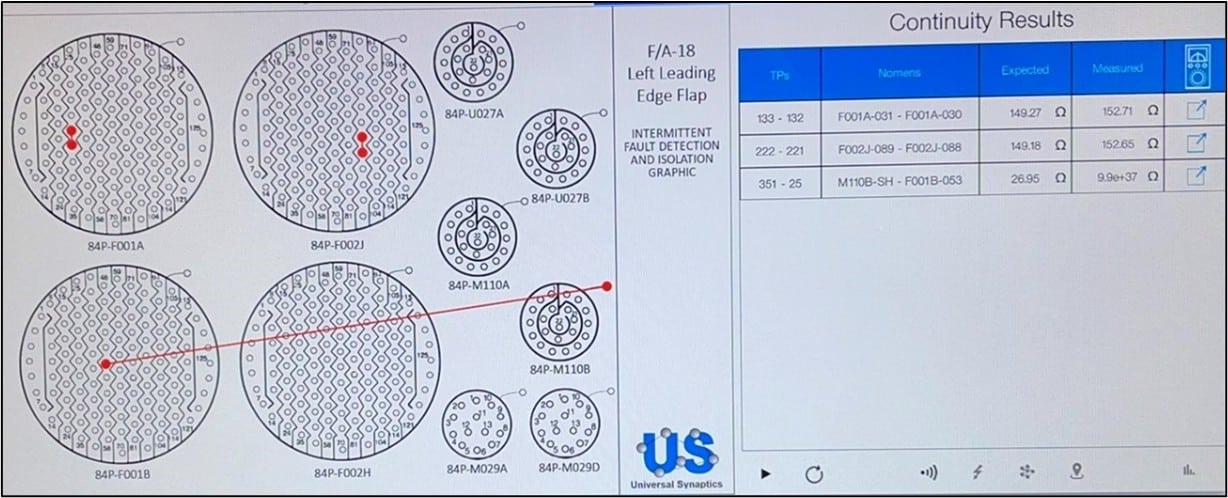
Figure 7 – Left Leading Edge Flap Continuity Results #1
The REDACTED / REDACTED / USC test team discussed why this could possibly be happening. From our training sessions, the group recalled the “curve of degradation” as outlined in Figure 1 above. A hard broke, open circuit does not instantaneously become such. It progresses from a low-level micro-break (Stage 1) intermittent issue, likely not yet causing an operational failure, into a true intermittent issue (Stage 2) failing in operation of the weapon system, that is testing as NFF and is undetectable by traditional processes of troubleshooting and deployed tools, such as ohmmeters or digital multimeters. This then degrades further with usage / wear and tear into a true hard faults or open circuit (Stage 3). Recommended course of action was to re-seat the UUT connectors and re-run Continuity test. These results are outlined in Figure 8 – Left Leading Edge Flap Continuity Results #2.
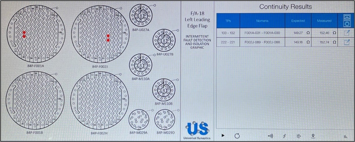
Figure 8 – Left Leading Edge Flap Continuity Results #2
The differences from Figure 7 to Figure 8 highlight an intermittent issue that, with stimulus such as disconnect/re-connect of connectors and/or movement of the UUT harness, is degrading and electrically behaving intermittently between a Stage 2 intermittent issue and Stage 3 semi-hard / hard fault. This is a great example of intermittent behavior and highlights why NFF is such a large cost driver and readiness degrader. Continuity testers were not built to detect and isolate intermittent issues that manifest in flight or on the ground with environmental stimulus. Figure 9 – Left Leading Edge Flap Intermittence Results highlights the differences between a Continuity test and the Intermittence test. It shows the power of the continuous and simultaneously monitoring of IFD technology. TP 351, M110B-SH quickly limited out at 50 intermittent events. IFD technology also pinpointed other intermittent issues on indicated TPs that traditional testing methods were incapable of finding.
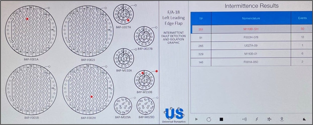
Figure 9 – Left Leading Edge Flap Intermittence Results
- Connectors 84P-U027A and 84P-U027B on the Left Leading Edge Flap had been removed entirely for outer wing removal on Aircraft Tail #REDACTED; exposed wires were taped together. Finalized map includes all schematic connections as if outer wing were installed.
- Connectors 84P-U028A and 84P-U028B on the Right Leading Edge Flap had been removed entirely for outer wing removal on Aircraft Tail #REDACTED; exposed wires were taped together. PIFD highlighted several shorted conditions during Shorts testing. Finalized map includes all schematic connections as if outer wing were installed.
- Database map comparison had been conducted by USC overnight on 9 Feb by USC and updated maps had been freshly updated and re-installed prior to testing on 10 Feb. First test of the day was conducted on the Right Aileron of Aircraft Tail #REDACTED. USC had renamed AutoMap configurations with an * special character. This prevented test reports from automatically saving due to the overarching Windows OS requirements. USC will ensure naming requirements are adhered to in the future to prevent report autosave issues.
Recommendations
- Utilize PIFD within REDACTED to simplify continuity and shorts testing while decreasing test time.
- Implement PIFD to enable repair actions for current NFF issues within the REDACTED / REDACTED procedures to detect and isolate intermittent issues that are currently going undetected by traditional deployed testing capabilities.
- Leverage PIFD as a Quality Assurance (QA) tool to validate cables and components before sell-off / validation testing.
- Verify completed repairs of EWIS cables and components as accurate and intermittent-free prior to releasing assets as ready for install on an aircraft.
- Deploy PIFD test sets to enable quick and comprehensive test outcomes, improve EWIS and component failure rates, increase overall efficiency of current test capability, and most importantly improve F/A-18 readiness for the REDACTED.
- Introduce PIFD test technology to other areas of use in the REDACTED portfolio. PIFD test technology is easily adaptable to production, manufacturing, quality assurance, and other repair procedures.
Summary
PIFD versatility and capabilities were highlighted during this delivery and training project, underscoring the technology’s abilities to build TPS maps automatically, detect and isolate intermittent faults, reduce maintenance time associated with the intermittence failure mode, remediate NFF test results, quality assure repair actions, and enhance overall depth of testing and efficiency.
IFD technology has proven to increase components and wiring system reliability. With continued use of the PIFD by REDACTED reliability of the REDACTED F/A-18 weapon system will increase by ensuring that open, shorted, and intermittent circuits are rapidly identified to allow for quick repair. This will have a major impact on the unnecessary wasted funds attributed intermittent issues that drive NFF test results.
Appendix 1
Appendix 2
Appendix 3
Appendix 4
Appendix 5
Appendix 6
Appendix 7
Appendix 8
Appendix 9
Appendix 10
Appendix 11
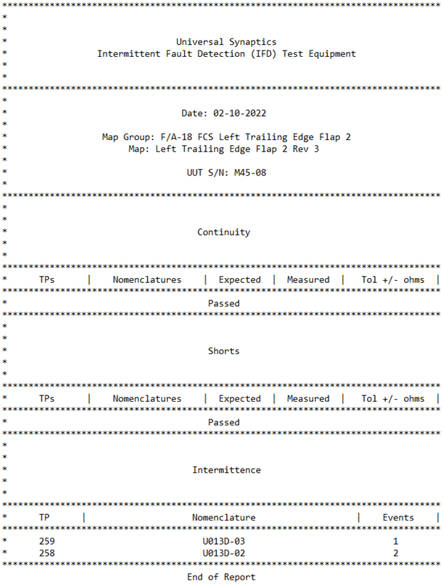
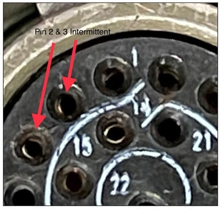
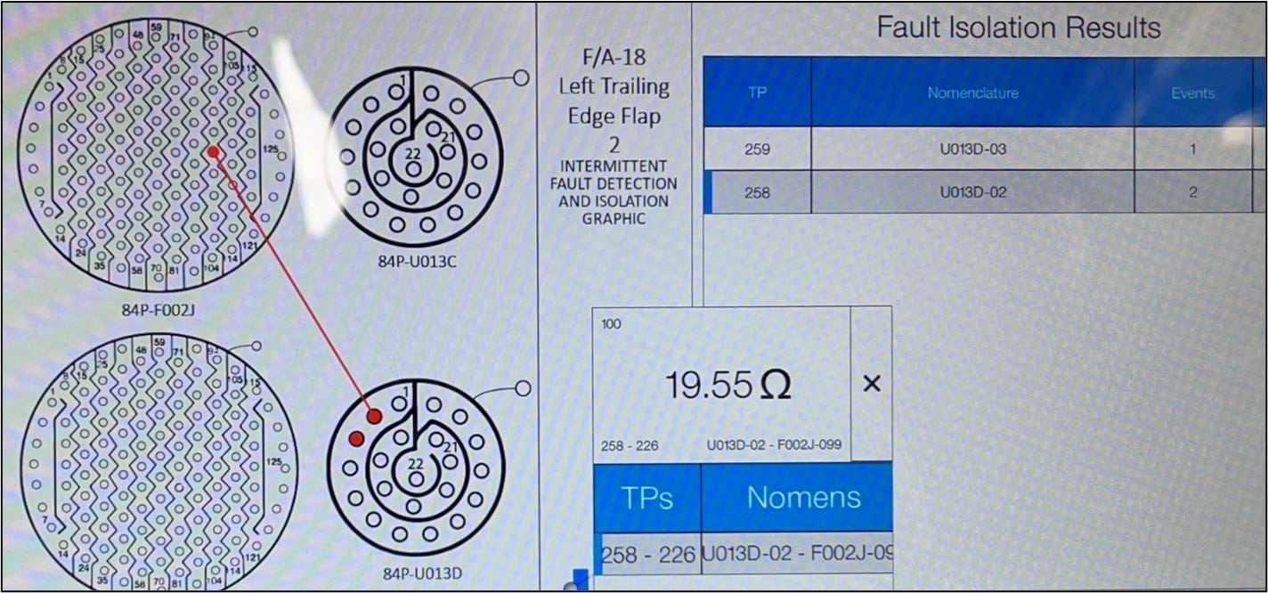
Intermittent issues on connector U013D, test points 258 and 259 were detected. Pin 2 experienced two intermittent events while Pin 3 experienced one intermittent event. These faults were visually taken to root cause during Fault Isolation immediately after detection and isolation in Intermittence mode. It appears that the pin receptables are bent to varying degrees causing intermittency when vibration was applied. This entire connector was worn and damaged yet passed all standard, conventional hard fault static tests. Other pin receptacles appear damaged yet were not behaving intermittently. It is recommended that these faults be put under magnification for further analysis before repair.
