Intermittent Fault Detector™ (IFD-256™) Test Summary
Wire Bundle Assembly 286W0751-302 / 286W0752-302
Introduction:
The subject harness provided by Air France Industries (AFI) was given to the Universal Synaptics (USC) / Barfield, Inc. team on site at Charles De Gaulle Airport – AFI Engine Maintenance Facility. Testing was conducted to demonstrate Intermittent Fault Detection™ (IFD™) technology and was coordinated by Barfield and AFI.
Selection of the GE90 wire bundle assembly was based on No Fault Found (NFF) rates and recurring unscheduled/unplanned maintenance costs caused by the 751/752 segments of the harness – a recent aircraft issue caused by the subject harness reached nearly $500K in maintenance costs. Harness S/N 6693415 was selected as the test case for demonstration after it was returned to AFI from the authorized repair facility as Serviceable and Ready for Install (RFI) in accordance with the approved maintenance manual and industry standard testing with conventional wire test methods (troubleshooting tools – Digital Multimeter (DMM), Megger and/or Automatic Test Equipment (ATE)).
Testing was conducted to demonstrate the advanced prognostic / diagnostic capability of IFD™ technology. USC and Barfield arrived with the Portable IFD™ test set and GE90 wire bundle assembly Interface Test Adapter (ITA), that was designed, developed, and manufactured by Universal Synaptics. No Test Program Set (TPS) was developed or required prior to arrival, due to the portable IFD’s AutoMap™ capability.
Test Procedures:
- AutoMap™ – discovered the Unit Under Test (UUT) true as-wired configuration
- S/N 6693415 was used as a baseline “gold” unit to establish UUT profile (feasible because the test asset was considered “serviceable” based on a standard functional test of ohmic resistance)
- Continuity – tested for open circuits and measures resistance against established AutoMap baseline (open circuits / high resistance tests)
- Shorts – provided shorts indication and shorts tracing
- Intermittence – monitored all circuits to detect and isolate all three Stages of intermittent faults (see Graphic 1)
- Fault Isolation – detected intermittent faults through programmatic isolation
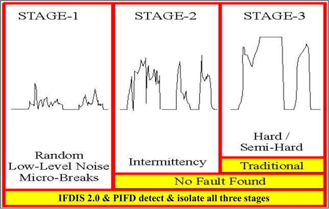
Graphic 1 – Three Stages of an Intermittent Fault
Stage 1 – random low-level nanosecond microbreaks, likely not operationally evident yet, but on curve of degradation to become Stage 2
Stage 2 – intermittent failure evident to pilot in operation, reported to ground crew, passes ground test and labeled No Trouble Found (NTF) or No Fault Found (NFF), on curve of degradation to become Stage 3
Stage 3 – semi-hard or hard failures, Automatic Test Equipment (ATE) and troubleshooting tools such as DMMs designed to detect hard faults (open circuits or shorted circuits)
Results:
S/N 6693415 – 286W0751-302
Test Date: 9 March 2020
- IFD-256 Continuity testing conducted – no open circuits present in the UUT
- IFD-256 Shorts testing conducted – no shorted circuits present in the UUT
- IFD-256 Intermittence testing conducted – multiple intermittent events (64 discrete intermittent events) detected on 03PN-P2-01, Test Point (TP) 49, Node 14 with light, manual manipulation of the harness (see Graphic 2); P2 connector with intermittent events can be viewed in Graphic 3 and 4. One intermittent event detected on GND-CP-03, TP 45, Node 43.
S/N 6693415 – 286W0752-302
Test Date: 9 March 2020
- IFD-256 Continuity testing conducted – no open circuits present in the UUT
- IFD-256 Shorts testing conducted – no shorted circuits present in the UUT
- IFD-256 Intermittence testing conducted – no intermittent faults present in the UUT with light, manual manipulation applied while IFD monitoring all circuits of the UUT simultaneously and continuously
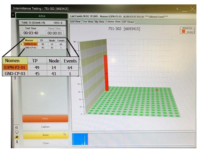
Graphic 2 – Intermittence Graphic – S/N 6693415 – 286W0751-302
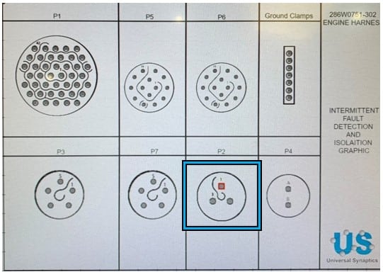
Graphic 3 – IFD Fault Isolation Graphic – GE90 Engine Harness P2 Connector
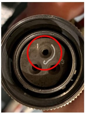
Graphic 4 – Actual P2 Connector
Recommendation:
- Utilize intermittent fault data provided from the IFD and visually take the detected and isolated intermittent failures to root cause. Attention should be given to the ground wire (Graphic 5 & 6) to cannon plug P2 as the location of the intermittent faults manifested when the technician provided light manual stimulus. The bend of the ground wiring appears to put excess stress on the material which is likely the cause of the intermittent events.
- Insert portable IFD testing into the AFI Fault Isolation Manual (FIM) and/or CMM to reduce NFF occurrences due to undetected and hence unrepaired intermittent faults – AFI released this GE90 wire harness with known intermittent faults back into service due to CMM test procedures.
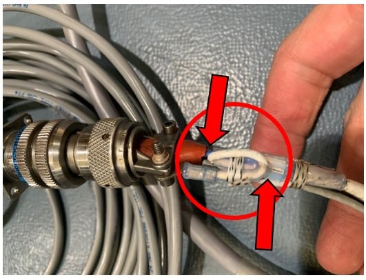
Graphic 5 – Ground Wire to P2 Connector
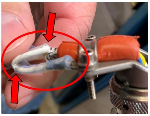
Graphic 6 – Ground Wire to P2 Connector
Observations:
- Conventional ATE / troubleshooting tools and techniques are severely limited and did not find these intermittent faults (see Graphic 1 – Three Stages of an Intermittent Fault)
- The portable IFD test deemed this GE90 wire harness to be unserviceable that requires a repair action before release to the aircraft – CMM procedures do not include troubleshooting for or repairing intermittent faults, therefore the wire harness was returned to service with a known intermittent fault
- When this wire harness fails in operation and returns to the repair facility, it will test No Fault Found (NFF) with current FIM / CMM testing procedures
Summary:
Universal Synaptics’ patented Intermittent Fault Detection technology has proven to increase aircraft component reliability. As proven by this demonstration, the IFD-256, once implemented, will increase the reliability of the aircraft by ensuring that open circuits, shorted circuits and intermittent circuits are not present in the wire bundle assemblies / engine harnesses installed on Boeing 777 GE90 engines flown and maintained by AFI.
The ability to detect and isolate intermittent faults in wiring harnesses and components, thus preventing Operational Difficulty Index (ODI) events and customer dissatisfaction, will save AFI on unnecessary expenses associated with NFF. The Air Transport Association (ATA) estimates NFF costs the commercial aviation industry $250,000 per year per aircraft. Testing wiring harnesses and components in accordance with the FIM or CMM designates them “serviceable” from a requirement perspective but does not solve the issues lurking beneath the surface that conventional test equipment and troubleshooting methodologies cannot detect and isolate.
Additional Information:
The USC / Barfield testing team was invited back to brief and demonstrate IFD technology for additional technicians and engineers on 10 March 2020. Harness 286W0751-302 was the only portion of the wire assembly tested by the portable IFD.
The same test procedures were followed with the same intermittent results manifesting on Connector 03PN-P2-01, Test Point (TP) 49, Node 14. The ability to conclusively replicate the same intermittent faults the next day indicates that the test subject wiring harness on the GE90 engine will most likely fail in operation.
Additional Test Photos:

Graphic 7 – USC CXO, Nate Johnson, and Technical Director, Tony Iseminger, in front of GE90 Engine installed on Boeing 777

Graphic 8 – Wire Bundle Assembly installed on GE90 Engine on Aircraft – in situ testing is preferable to allow UUT to function in installed environment to simulate real world environment
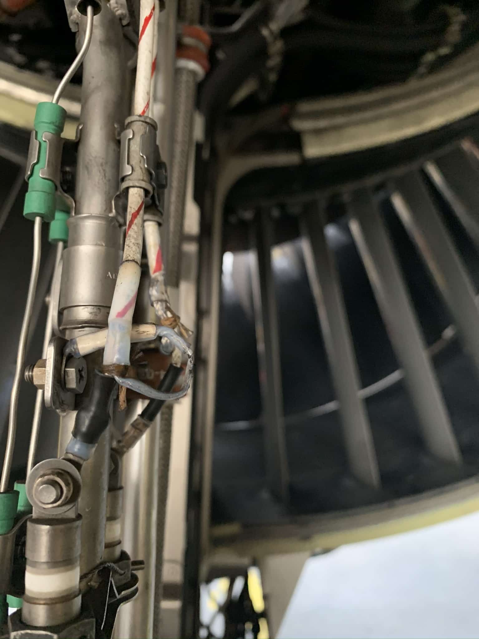
Graphic 9 – Wire Assembly installed on GE90 Engine – excessive wire bend prone to degradation and intermittence
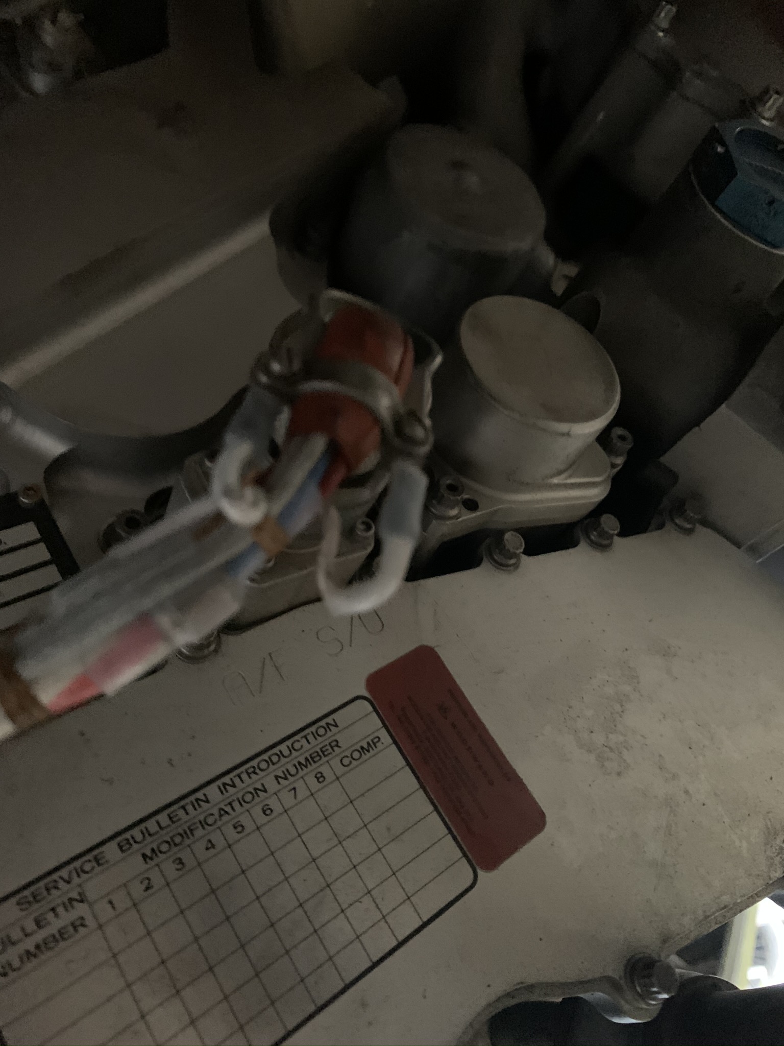
Graphic 10 – Wire Assembly installed on GE90 Engine – possible excess wiring causes excessive bends prone to intermittent behavior
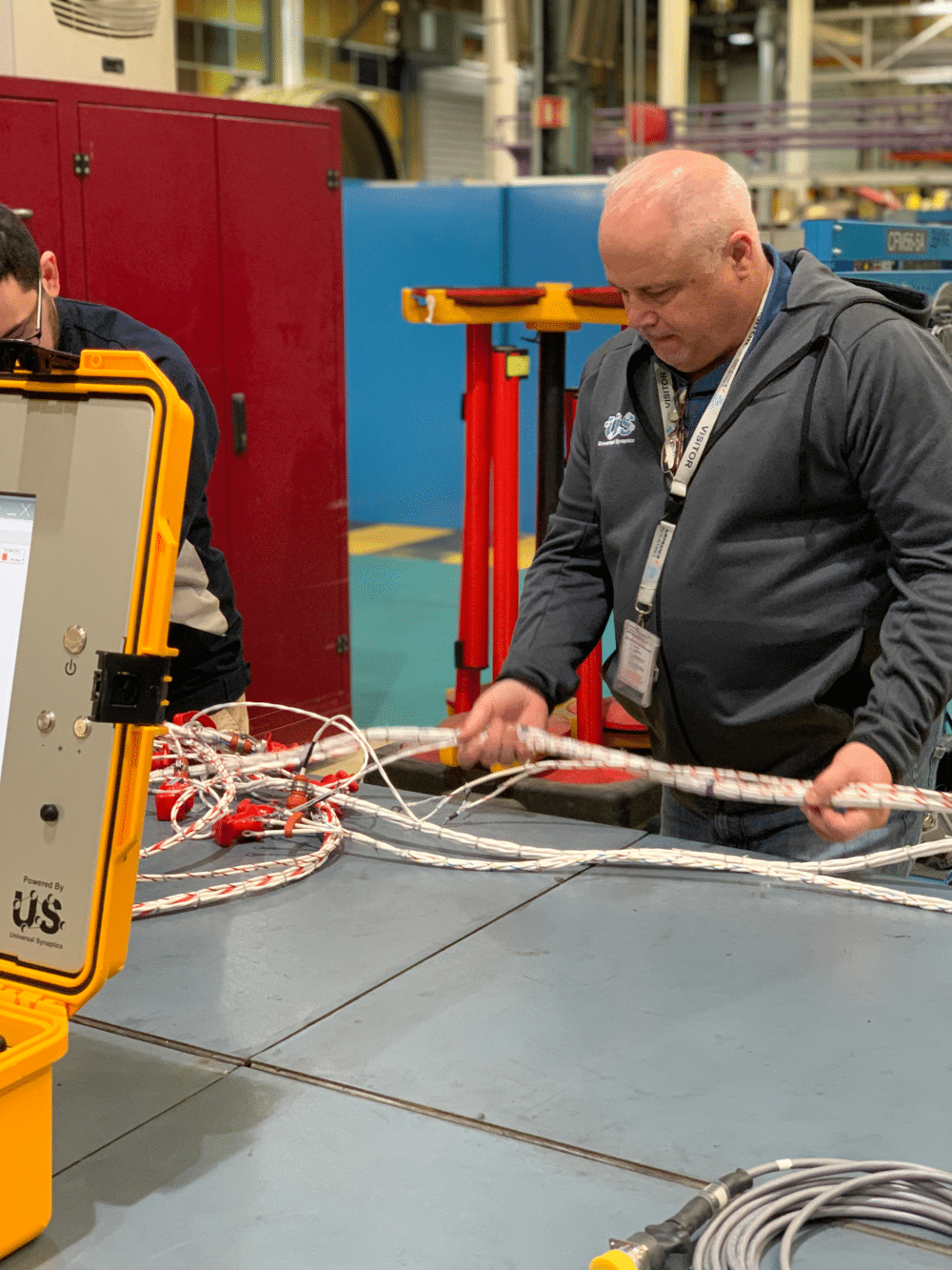
Graphic 11 – USC Technical Director, Tony Iseminger, connecting Wire Bundle Assembly to IFD interface test adaptor (ITA)
