Portable Intermittent Fault Detector™ (PIFD-512™)
REDACTED
Crash Barrier Operations Test Summary
Introduction
Universal Synaptics (USC) performed Portable Intermittent Fault Detector™ (PIFD™) testing on site for the REDACTED Crash Barrier Operations team on 20 – 21 September 2021 with representatives in attendance from the Crash Barrier Operations team.
The Crash Barrier Operations team troubleshooting process leverages conventional test equipment built to detect hard faults in wiring cables that connect Anthropomorphic Test Devices (ATD) to Data Acquisition Units (DAU) on-board prototype crash vehicles. The team has robust procedures with currently deployed processes and deployed equipment and does an excellent job maintaining thousands of cables and ATDs to provide a high level of data fidelity for vehicle certification purposes. The overarching crash test process, however, does suffer from data dropout caused by intermittent events that the group identifies by monitoring DAU data collection. Automatic processes that sense data dropout allow for test aborts that help in remediating the complete loss of a crash test vehicle and the associated lifecycle costs of testing. Complete failures do occur due to intermittent issues and some tests are unfortunately a complete loss. The team is very proficient at identifying suspect cables and areas of failure, but faults often test No Trouble Found (NTF) or No Problem Found (NPF) when the suspect cable set is tested using currently fielded test capability. Current diagnostic process is also reactive in nature, meaning that faults are only identifiable after they become operationally evident causing issues.
The implementation of the PIFD into the REDACTED Crash Barrier Operations test process will increase overall data collection fidelity by reducing data dropout failures, improve test data accuracy, reduce NTF and NPF test results, and provide the ability to rapidly detect and isolate opens, shorts, and intermittent faults that negatively impact current test processes. Significant reductions in qualification test time will also be achievable as intermittent-free assets will easily pass go/no-go, pass/fail validation tests that are required prior to performing a crash test.
Testing was conducted to demonstrate the advanced prognostic and diagnostic capability of the only approved MIL-PRF-32516 performance specification and the PIFD’s applicability to the Crash Barrier Operations test procedures. USC supplied a PIFD-512 and demonstration Interface Test Adapter (ITA) built with opposite gender mating connectors for the DAU. Minimal data was provided, and no Test Program Set (TPS) was developed prior to arrival, thus demonstrating the PIFD’s AutoMap™ capability.
IFD Test Procedures
- AutoMap – discovered the as-wired configuration of 15 different test assets and test scenarios leveraging REDACTED supplied cables, accelerometers, and loop back plugs
- Continuity – tested for open circuits and measured resistance against established AutoMap baseline (open circuits / high resistance tests)
- Shorts – provided shorts indication and shorts tracing
- Intermittence – monitored all circuits simultaneously and continuously to detect and isolate all Three Stages of an Intermittent Fault (Figure 1)
- Fault Isolation – programmatic isolation of detected intermittent faults
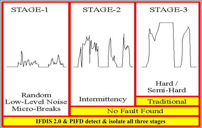
Figure 1 – Three Stages of an Intermittent Fault
Stage 1 – random low-level nanosecond microbreaks, likely not operationally evident yet, but on curve of degradation to become Stage 2
Stage 2 – intermittent failure evident to pilot in operation, reported to ground crew, passes ground test and labeled No Trouble Found (NTF) or No Problem Found (NPF) on curve of degradation to become Stage 3
Stage 3 – semi-hard or hard failures, Automatic Test Equipment (ATE) and troubleshooting tools such as DMMs designed to detect hard faults (open circuits or shorted circuits)
Connecting the Interface Test Adapter (ITA)
The ITA provided for this demonstration has four (4) sections with each having one d-sub end (J1-J4) that connects to the PIFD (Figure 2) and a cannon plug end (P1-P4) that plugs into to the extension cables (Figure 3). J1 through J4 on the ITA connect to matching jacks J1 through J4 on the PIFD. P1 through P4 connect to each of the four (4) cannon plugs on the extension cables.

Figure 2 – D-Subs to PIFD

Figure 3 – Cannon to Extension Cables
Test Plan and Procedures
- AutoMap™
- AutoMap™ is performed as follows to discover the as-wired configuration of the UUT.
- Login as Advanced Technician.
- Select the appropriate map from the group.
- Run Automap.
- Log out of Advanced Technician.
- AutoMap™ is performed as follows to discover the as-wired configuration of the UUT.
- Conventional Tests
- Conventional continuity and shorts tests are performed while the UUT is in a static state to evaluate the general condition of the UUT. The operator may choose to halt testing and repair any hard opens or shorts before proceeding to the intermittence testing section. Conventional tests are performed as follows.
- Select appropriate map with the highest Rev from Map Group.
- Press Start button to run Continuity and Shorts testing.
- Address any open or shorted circuits.
- Conventional continuity and shorts tests are performed while the UUT is in a static state to evaluate the general condition of the UUT. The operator may choose to halt testing and repair any hard opens or shorts before proceeding to the intermittence testing section. Conventional tests are performed as follows.
- Intermittence Testing
- Intermittence Testing will start automatically if no open or shorted circuits are present in the UUT. This test differs from the conventional scanning tests because it is a constant monitoring of all electrical paths simultaneously. The testing period is determined by the time it takes to run through the environmental and vibrational profile or manual manipulation of the UUT, as desired. Intermittent fault events will show in RED located on the Fault Isolation Graphic as highlighted below (Figure 4).
- Begin environmental stimulation process for the UUT or the manual manipulation process while intermittence testing is active. Intermittent faults will be displayed in real time.
- Fault Isolation
- Perform Fault Isolation to begin to identify root cause(s) for the intermittent faults.
- Reports
Detected and Isolated faults discovered during PIFD testing will be compiled and exported to the “Reports” folder on the PIFD Desktop.

Figure 4 – PIFD Fault Isolation Graphic
Results
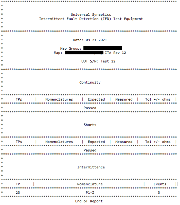
- PIFD AutoMap executed on Crash Operations UUTs – as-wired configuration of all UUTs discovered each time in less than one minute
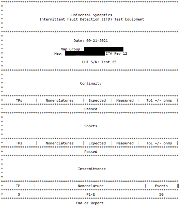
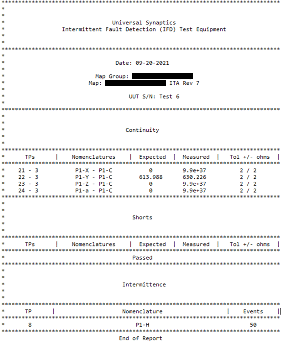
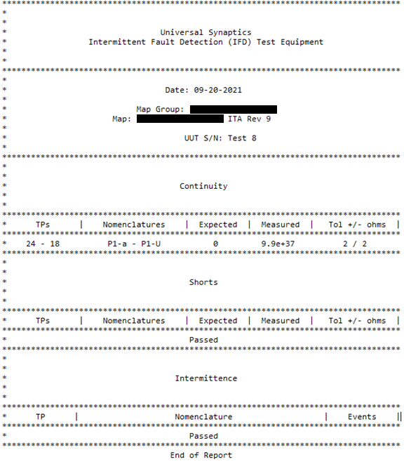
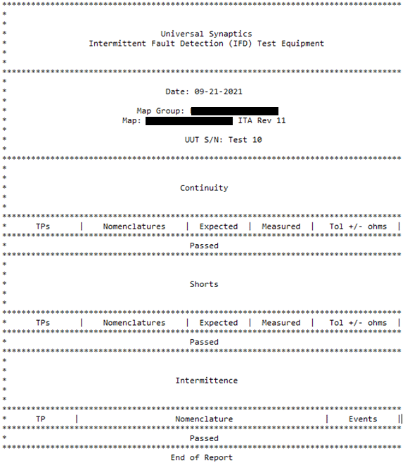
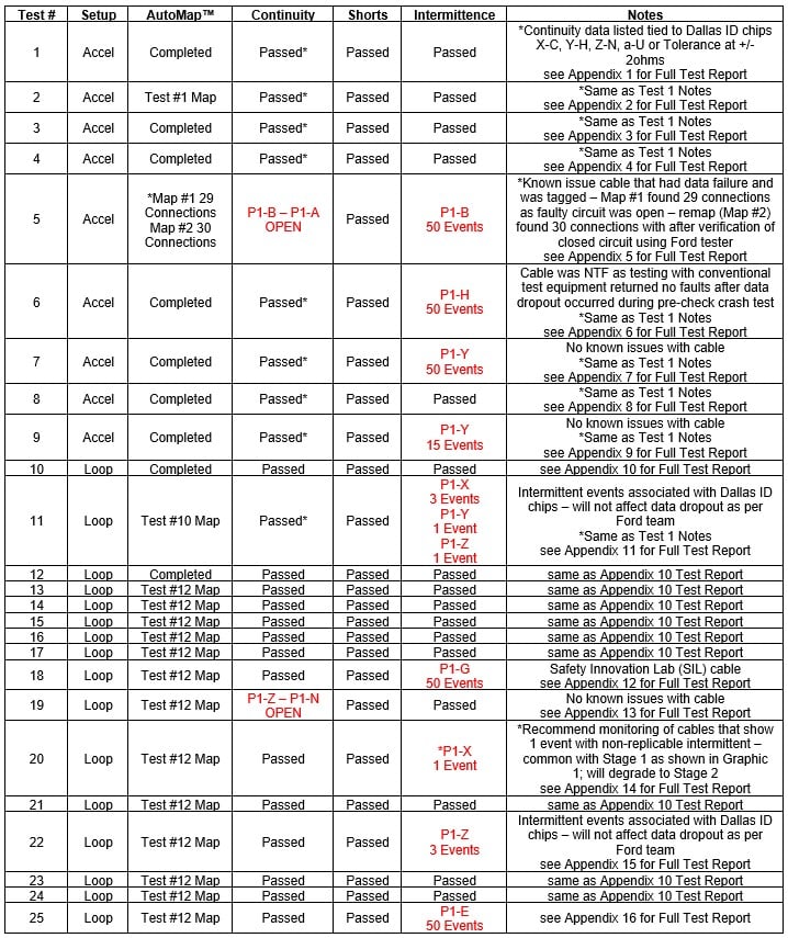
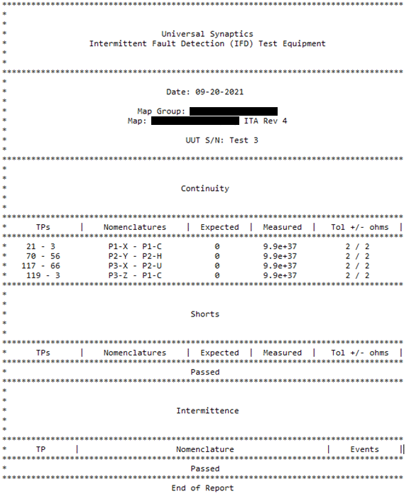
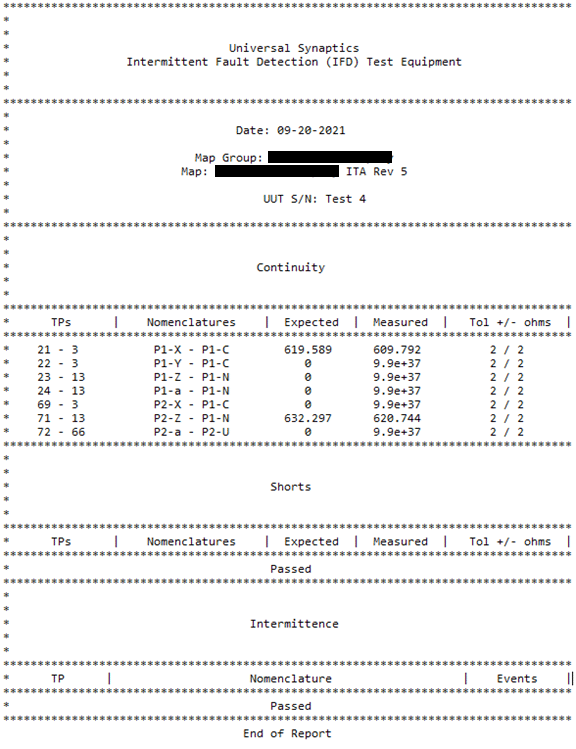
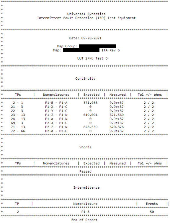
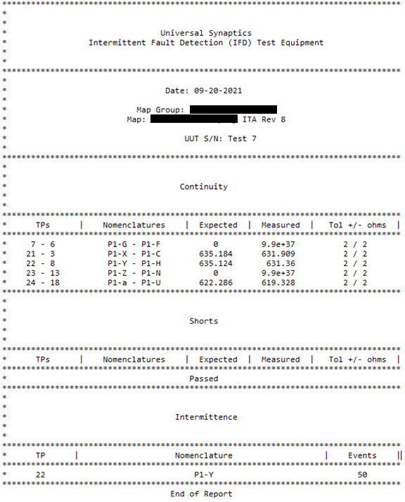
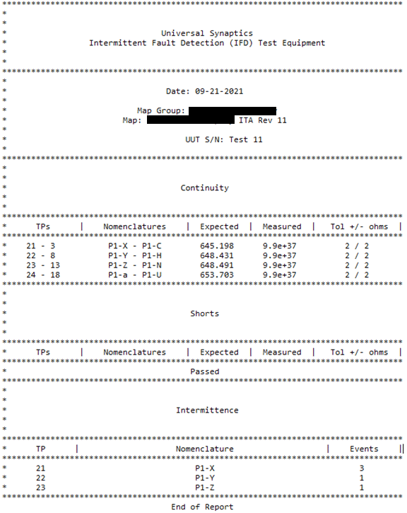
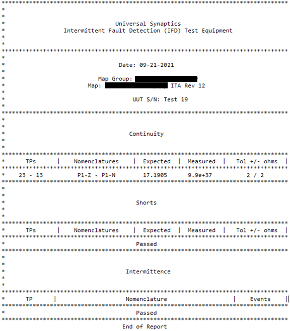
- PIFD Continuity testing conducted – see Table 1 for specific UUT test results
- PIFD Shorts testing conducted – see Table 1 for specific UUT test results
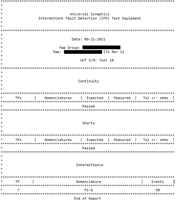
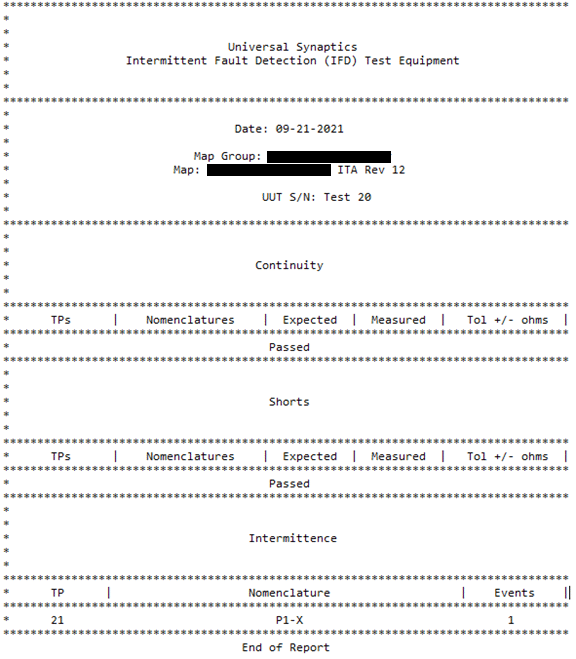
- PIFD Intermittence testing conducted – see Table 1 for specific UUT test results
- PIFD Fault Isolation – intermittent faults were not taken to root cause as the purpose of this demonstration was to highlight the PIFD test regime – cables that had intermittent issues were tagged appropriately to allow the Crash Barrier Operations team to repair later

Figure 5 – Sample Intermittence Test Screen from Test #5 – red pin indicates intermittent fault location
Table 1 – Test Results
Lessons Learned
- The PIFD-512 provides adequate coverage of needed circuit connections to test a complete ATD all at once with recommended environmental stimulus. The test demonstration team utilized a simple vibration tool to allow the intermittent issues to manifest. An ITA to connect to a complete ATD setup is feasible.
- Test 6, where cable was NTF and had been tested for several hours prior to IFD demonstration testing, quickly reached the 50 intermittent events limit on P1-H. This cable was taken to the REDACTED cable tester to see if it could duplicate what the Portable IFD found. During this test, it was pointed out by USC that the tester was visibly scanning through each circuit and would not detect any intermittent issues, even with flexing the cable, due to the scanning of one circuit at a time with low test sensitivity in the milliseconds range. No issues were detected by the REDACTED cable tester.
- The Fault Isolation Graphic, which allows for pinpoint precision location of the precise fault or faults, for this demonstration project pictures four 26-pin connectors (see Figure 5). The 6-pins connectors on the Four Channel Input Cables are more beneficial to include on the graphic as those connectors lead into the different accelerometers of the test units.
- The Dallas Self ID Chips are not necessary to include on any IFD Map and have no need to be tested. USC recommends shutting up these test points on initial map build as the Crash Barrier Operations team does not need to test these connections.
- Current test process, enabled by the Dallas Self ID Chips, allows for rapid connection of any Four Channel Input Cable to be connected randomly to the ATD to save time. Initial IFD test setup and map can accommodate random connection test setup by widening the tolerances of the connections to accelerometers (up to 1K ohms). While this is not ideal for the automated Continuity test conducted by the PIFD, it will not affect the intermittence test on these circuits associated with the accelerometers. Current Crash Barrier Operations test procedures and technology provides Continuity testing coverage as well. Demonstration test tolerances were a default +/- 2ohms and can be adjusted to fit desired test requirements.
- Crash Barrier Operations team indicated accelerometers utilized were roughly 25% Endevco (<1K ohms) and 75% MSI (>1K ohms). IFD technology will not test above 1K ohms, however, two MSI components were identified in AutoMap showing less than their specification at around 750-800 ohms, thus making them candidates for test. It is recommended that additional MSI accelerometers be mapped for similar testability. It was also mentioned that MSI components may be phased out through attrition.
- Two types of ATD were assessed. All demonstration tests conducted were on the more common ATD with no built-in DAUs. The less common, more expensive ATD was assessed and defined as an excellent PIFD test candidate with ease of interfacing to the built-in DAU connectors.
Recommendations
- Utilize PIFD within the REDACTED Crash Barrier Operations to simplify continuity and shorts testing while decreasing test time.
- Implement PIFD to enable repair actions for current NTF and NPF issues within the Crash Barrier Operations procedures to detect and isolate intermittent issues that are currently going undetected by traditional deployed testing capabilities.
- Leverage PIFD as a Quality Assurance (QA) tool to validate cables and components before qualification testing prior to crash test launches.
- Verify completed repairs of cables and components as accurate and intermittent-free prior to releasing assets back into the testing field.
- Deploy PIFD test sets to enable quick and comprehensive test outcomes, reduce crash test failure rates with complete data loss, and increase overall efficiency of current test capability.
- Introduce PIFD test technology to other areas within the REDACTED, as highlighted by the tests conducted with the Safety Innovation Lab (SIL) assets. PIFD test technology is easily adaptable to production, manufacturing, quality assurance, and other repair procedures.
Summary
PIFD versatility and capabilities were highlighted during the demonstration tests conducted, underscoring the technology’s abilities to detect and isolate intermittent faults, reduce maintenance time associated with the intermittence failure mode, remediate NTF and NPF test results, quality assure repair actions, and enhance overall depth of testing and efficiency.
IFD technology has proven to increase components and wiring system reliability. As demonstrated, the PIFD, once implemented, will increase the reliability of the REDACTED Crash Barrier Operations harnesses, cable sets, and components by ensuring that open, shorted, and intermittent circuits are rapidly identified. This will have a major impact on the unnecessary wasted funds attributed to the organization’s intermittent issues during crash test preparation, setup, and testing.
Appendix 1
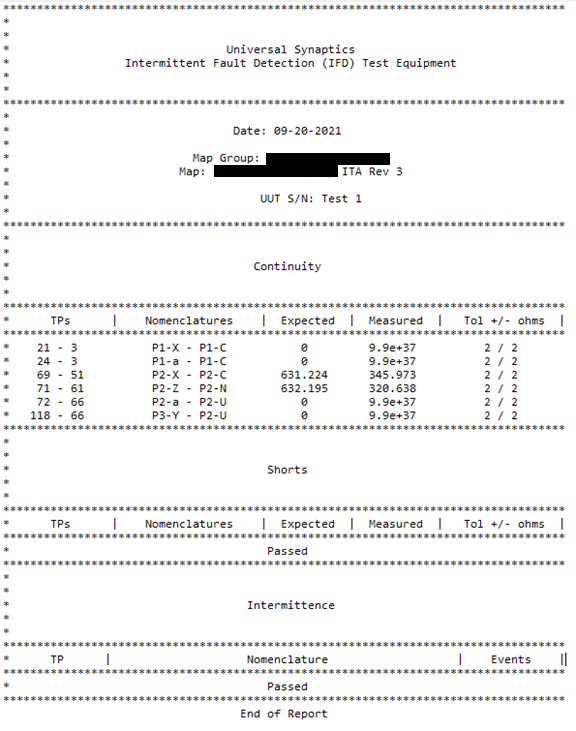
Appendix 2
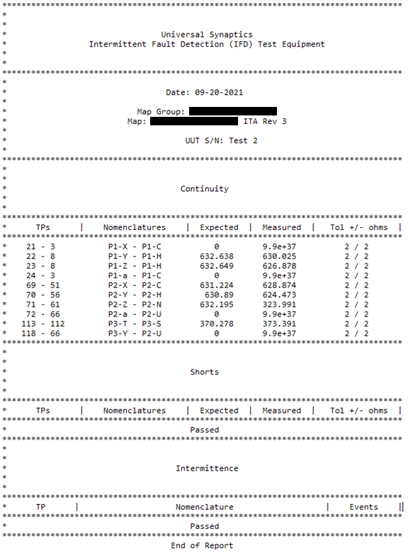
Appendix 3
Appendix 4
Appendix 5
Appendix 6
Appendix 7
Appendix 8
Appendix 9
Appendix 10
Appendix 11
Appendix 12
Appendix 13
Appendix 14
Appendix 15
Appendix 16
