Commercial Technologies for Maintenance Activities (CTMA)
A-10 Intermittent Fault Detector™ (IFD™) Test Summary
Introduction:
Universal Synaptics participated in A-10 testing to showcase Intermittent Fault Detection (IFD) technology on USG selected harnesses. Testing occurred on 19 April, 7 June, and 11 November 2018. This is report summarizes the testing that occurred.
Summary Notes / Out Brief – 19 April 2018
A-10 Control Stick Grip (CSG) P/N: 89954SOCN362A2688P1
S/N: 123064
The A-10 Control Stick Grip (CSG) was selected by the Hill AFB / Universal Synaptics Team as the first Unit Under Test (UUT) for the Portable Intermittent Fault Detector (PIFD).
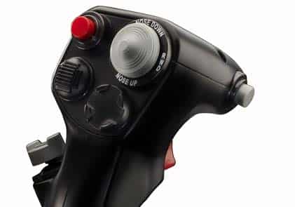
A-10 Control Stick Grip (CSG)
P/N: 89954SOCN362A2688P1
S/N: 123064
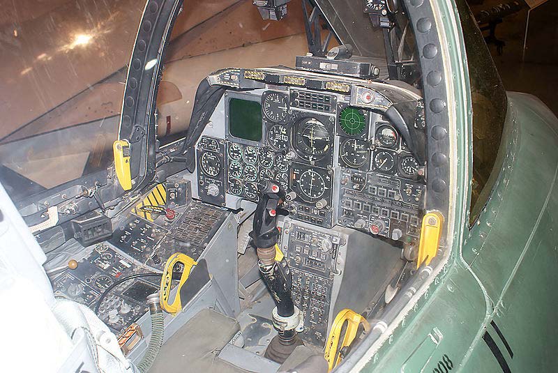
A-10 Control Stick Grip (CSG) Cockpit
Test Procedures:
- AutoMap™ – discover the Unit Under Test (UUT) true as-wired configuration
- Continuity – test for open circuits and measure resistance against established AutoMap baseline (open circuits / high resistance tests)
- Shorts – provide shorts indication and shorts tracing
- Intermittence – monitor all circuits to detect and isolate all three Stages of intermittent faults (see Graphic 1)
- Fault Isolation – detect intermittent faults to root cause through programmatic isolation
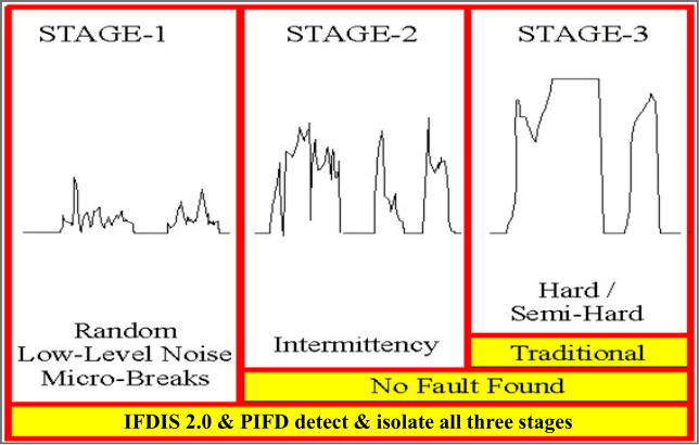
Graphic 1 – Three Stages of an Intermittent Fault
Stage 1 – random low-level nanosecond microbreaks, likely not operationally evident yet, but on curve of degradation to become Stage 2
Stage 2 – intermittent failure evident to pilot in operation, reported to ground crew, passes ground test and labeled No Trouble Found (NTF) or No Fault Found (NFF), on curve of degradation to become Stage 3
Stage 3 – semi-hard or hard failures, Automatic Test Equipment (ATE) and troubleshooting tools such as DMMs designed to detect hard faults (open circuits or shorted circuits)
- Utilizing the AWTS patch cable that connects the Portable IFD to the existing AWTS CSG interface cable the following test functions were performed:
- AutoMap function was performed to map the AWTS interface cable
- A standard continuity test on the AWTS interface cable was performed and the AWTS interface cable passed continuity testing
- Intermittence testing was performed on the AWTS CSG interface cable and the AWTS interface cable passed intermittence testing
- AutoMap function was performed to map the A-10 Control Stick Grip (CSG)
- A standard continuity check on the A-10 CSG was performed and the A-10 CSG passed continuity testing
- Intermittence testing was performed on the A-10 CSG and the A-10 CSG passed intermittence testing
- Intermittence was detected in the A-10 CSG by pulling the trigger and moving the Nose Down / Nose Up control button. Intermittent events were expected as these switches and triggers are intermittent by design in order to function properly. Some switch bounce was detected; however, the Joint Team believes this bounce is at an acceptable level due to the required function of the CSG
As part of the collaboration between Hill AFB and Universal Synaptics a discussion took place after the A-10 CSG testing about the universality of the AWTS Patch Cable. The Hill AFB Team inquired about the AWTS patch cable’s ability to connect to additional Interface Test Adaptors (ITAs) for an A-10 test set called the Portable Automated Test Station Model 70 (PATS-70).
The PATS-70 is a robust, flight line qualified test set that has gone through rigorous MIL-STD-810G, and MIL-STD-416F environmental testing. While it was developed to function as maintenance support equipment for the A-10C aircraft, it has no A-10 specific components so it can be adapted for maintenance on other aircraft, platforms, or systems.
The PATS-70 interface cable utilizes a MIL-STD 38999 connector similar to the AWTS interface cable; a fit check was conducted to determine the PIFDs ability to connect to it in order to test wiring systems currently tested by the PATS-70. The patch cable passed fit checks and it was decided by the group to include the PATS-70 interfaces in the test project to expand the demonstration of the PIFD on A-10 systems.
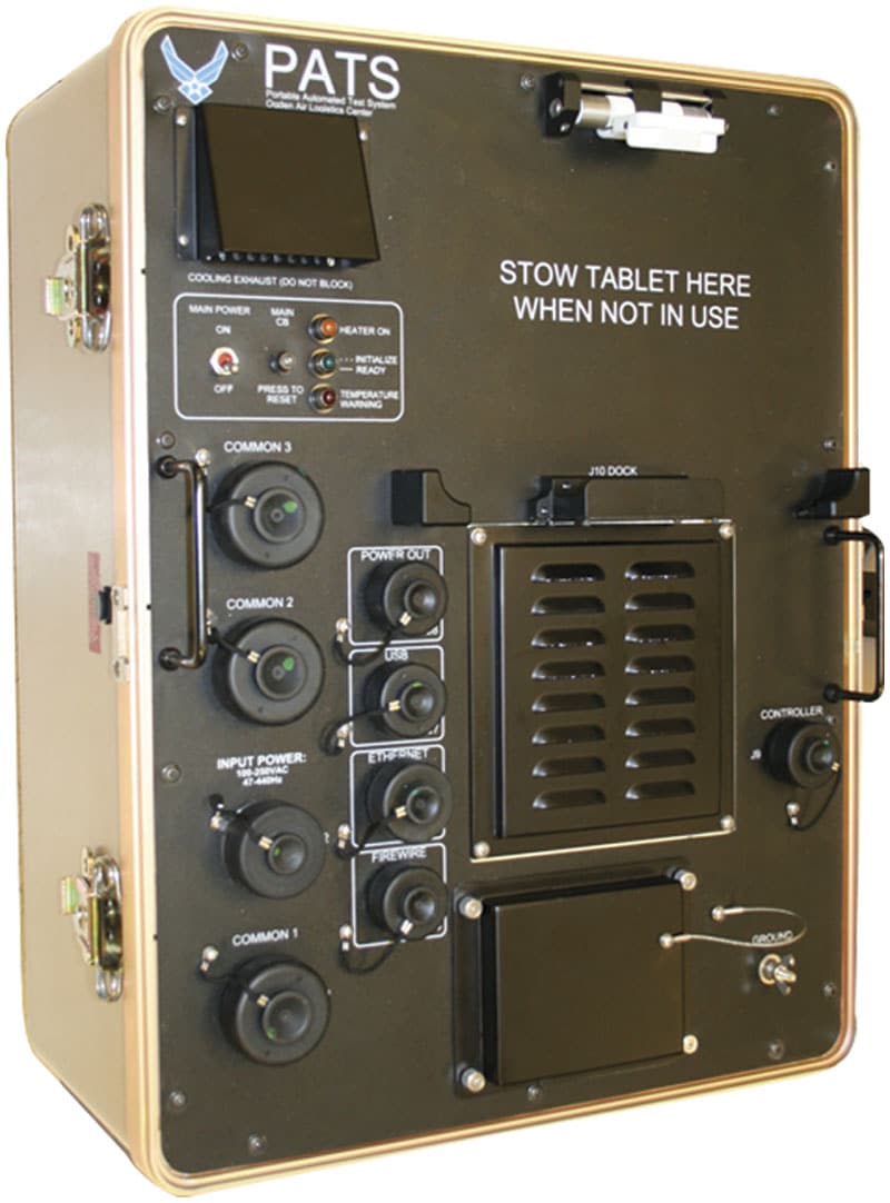
Portable Automated Test Station Model 70 (PATS-70)
The A-10 Armament Wiring Harness was selected by the Hill AFB / Universal Synaptics Team as the first Unit Under Test (UUT) for the Portable Intermittent Fault Detector (PIFD) utilizing the PATS-70 interface cables.
- Utilizing the AWTS patch cable the PIFD was able to interface into the existing PATS-70 Armament Wiring Harness interface cable. The following test functions were performed:
- AutoMap function was performed to map the PATS-70 interface cable – P/N: 201227762-10
- Standard continuity check on the PATS-70 interface cable was performed and the PATS-70 interface cable passed continuity testing
- Intermittence testing was performed on the PATS-70 interface cable and intermittence was detected and isolated on wires 35, 37, 53 and 63 (all two-point Nodes) – wire 63 had the most intermittent events, reaching the intermittent “glitch limit” set before the PIFD intermittent test at 50 intermittent events
Due to the intermittent faults detected and isolated in the PATS-70 interface test adaptor, the Team was faced with two options:
- Stop all further testing until the PATS-70 interface test adaptor was repaired
- Test the A-10 Armament Wiring Harness with the intermittent faults in the interface test adaptor logged – if an intermittent was detected and isolated on the A-10 Armament Wiring Harness at wire 35, 37, 53 or 63, the test results would require additional investigation as the intermittent events would most likely be registering due to the intermittence previously detected in the PATS-70 interface test adaptor
- Utilizing the AWTS patch cable we connected the Voyager to the existing PATS-70 interface cable and then into the A-10 Armament Wiring Harness. The following test functions were performed:
- AutoMap function was performed to map the A-10 Armament Wiring Harness
- Standard continuity check on the A-10 Armament Wiring Harness was performed and the A-10 Armament Wiring Harness passed continuity testing
- Intermittence testing was performed on the A-10 Armament Wiring Harness and four intermittent events were detected and isolated on wire 33. Intermittence was also detected and isolated on wires 35, 37, 53 and 63, which are the same intermittent events detected in the PATS-70 interface test adaptor
- Test data was logged and a second Intermittence test was run. One intermittent event was detected and isolated on wire 33. Intermittent events were also detected in wires 35, 37, 53 and 63 (ITA intermittent faults)
19 April 2018 Summary:
The Hill AFB and Universal Synaptics Team concluded a successful first day. It was agreed that it would benefit the A-10 PIFD Testing Project to utilize both AWTS interface cables and PATS-70 interface cables. Utilizing interface test adaptors from the AWTS and PATS-70 test sets provides access to a wide variety of wiring systems on the A-10 that the Portable Intermittent Fault Detector (PIFD) can test for intermittent faults.
The PIFD conclusively detected and isolated intermittent faults, performed continuity testing, and AutoMap was utilized for all test cases, including the Government provided interface test adaptors.
Summary Notes / Out Brief – 7 June 2018
Based on previous testing held 19 Apr 2018 (see “CTMA A-10 Project_Summary Notes_Out Brief 19Apr2018) when Hill AFB and Universal Synaptics used the AWTS patch cable to interface with additional Interface Test Adaptors (ITAs) for an A-10 test set called the Portable Automated Test Station Model 70 (PATS-70), additional testing was desired utilizing other PATS-70 cables.
The PATS-70 is a robust, flight line qualified test set that has gone through rigorous MIL-STD-810G, and MIL-STD-416F environmental testing. While it was developed to function as maintenance support equipment for the A-10C aircraft, it has no A-10 specific components so it can be adapted for maintenance on other aircraft, platforms, or systems.
The PATS-70 interface cable utilizes a MIL-STD 38999 connector similar to the AWTS interface cable; a fit check was conducted to determine the VIFDs ability to connect to it in order to test wiring systems currently tested by the PATS-70. The patch cable passed fit checks and it was decided by the group to include the PATS-70 interfaces in the test project to expand the demonstration of the PIFD on A-10 systems.
The A-10 Portable Automated Test Station Model 70 (PATS-70) Common Umbilical Cable was selected by the Hill AFB / Universal Synaptics Team as the first PATS-70 cable for the Portable Intermittent Fault Detector (PIFD).


Portable Automated Test Station Model 70 (PATS-70)
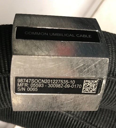

PATS-70 Common Umbilical Cable
P/N: 201227535-10
S/N: 0065
- Utilizing the AWTS patch cable, the PIFD was able to interface into the PATS-70 Common Umbilical Cable. The following test functions were performed on two unique cables:
- AutoMap function was performed to map the PATS-70 interface cable #1 – P/N: 201227535-10
- Standard continuity check on the PATS-70 interface cable #1 was performed and the PATS-70 interface cable passed continuity testing
- Intermittence testing was performed on the PATS-70 interface cable #1 and the cable was certified as intermittent free.
- AutoMap function was performed to map the PATS-70 interface cable #2 – P/N: 201227535-10
- Standard continuity check on the PATS-70 interface cable #2 was performed and the PATS-70 interface cable passed continuity testing
- Intermittence testing was performed on the PATS-70 interface cable #2 and the cable had intermittency on test point 123, node 84.
Due to the intermittent faults detected and isolated in the PATS-70 interface cable #2, any PATS-70 test completed with that cable would be suspect until repaired and certified as intermittent free on the PIFD.
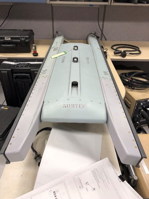

A-10 on Aircraft Assembly
2 Launcher Assembly Units (LAU)
1 Dual Rail Assembly (DRA)
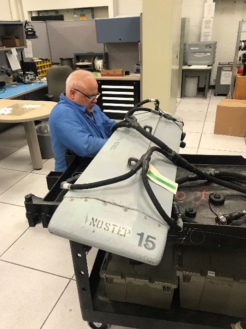

Technician Connecting PATS-70 Cable to DRA
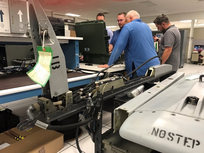

PIFD Connected to LAU via PATS-70 Cable
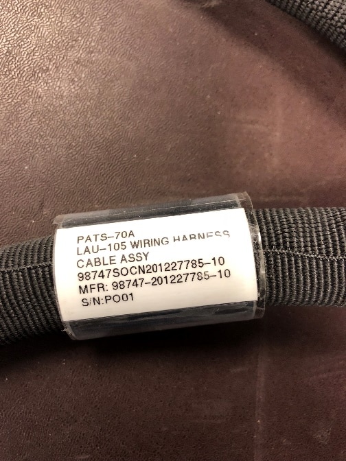

PATS-70 LAU-105 Wiring Harness Cable Assy
P/N: 201227785-10
S/N: PO01
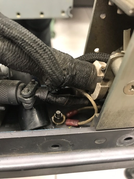

A-10 LAU – Intermittence Detected in Cannon Plug Wire Connection
- Utilizing the AWTS patch cable we then connected the Voyager to the existing PATS-70 interface cable called the LAU-105 Wiring Harness Cable Assy and then into the A-10 Launcher Assembly Unit (LAU-105). The following test functions were performed:
- AutoMap function was performed to map the A-10 LAU-105 Wiring Harness Cable Assy
- Standard continuity check on the A-10 LAU-105 Wiring Harness Cable Assy was performed and the harness passed continuity testing
- Intermittence testing was performed on the A-10 LAU-105 Wiring Harness Cable Assy and the harness passed intermittence testing
- AutoMap function was performed to map the A-10 LAU through the verified intermittent-free PATS-70 cable
- Standard continuity check on the A-10 LAU was performed through the verified intermittent-free PATS-70 cable and the A-10 LAU passed continuity testing
- Intermittence testing was performed on the A-10 LAU through the verified intermittent-free PATS-70 cable and the A-10 LAU failed intermittence testing; intermittence was detected and isolated on:
- J1-065 node 16
- J1-053 node 20
- J1-040 node 16
- J1-063 node 8
- J1-048 node 8
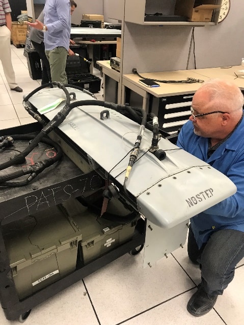

Technician Connecting PATS-70 Cable to DRA
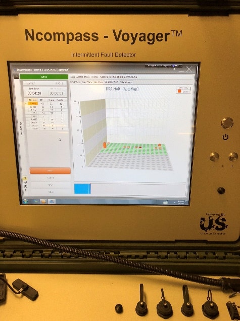

IFD Display Screen Indication of Intermittent Faults in the DRA UUT
- Utilizing the AWTS patch cable, we then connected the PIFD to the existing PATS-70 interface cable called the DRA Wiring Harness Cable Assy and then into the A-10 DRA. The following test functions were performed:
- AutoMap function was performed to map the A-10 DRA Wiring Harness
- Standard continuity check on the A-10 DRA Wiring Harness was performed and the harness passed continuity testing
- Intermittence testing was performed on the A-10 DRA Wiring Harness and the harness passed intermittence testing
- AutoMap function was performed to map the A-10 DRA through the verified intermittent-free PATS-70 cable
- Standard continuity check on the A-10 DRA was performed through the verified intermittent-free PATS-70 cable and the A-10 DRA passed continuity testing
- Intermittence testing was performed on the A-10 DRA through the verified intermittent-free PATS-70 cable and the A-10 DRA failed intermittence testing; intermittence were detected and isolated on:
- J1-065 node 32
- J1-031 node 13
- J1-062 node 13
- J1-054 node 27
- J1-001 node 1
- J1-055 node 29
- J1-057 node 28
- J1-063 node 6
- J1-058 node 29
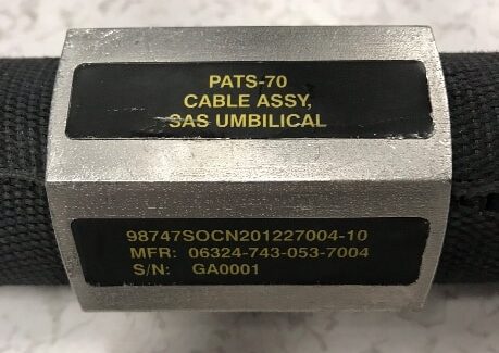

PATS-70 Cable Assy SAS Umbilical
P/N: 201227004-10
S/N: GA001
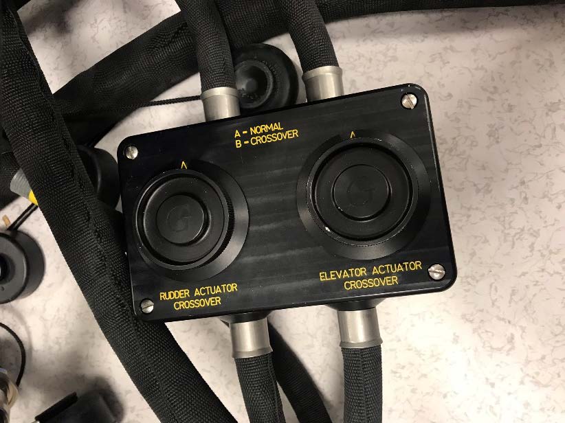

SAS Umbilical Rudder Actuator Crossover and Elevator Actuator Crossover
- Utilizing the AWTS patch cable, we then connected the PIFD to the existing PATS-70 interface cable called the Cable Assy SAS Umbilical. The following test functions were performed:
- AutoMap function was performed to map the A-10 Cable Assy SAS Umbilical
- Standard continuity check on the A-10 Cable Assy SAS Umbilical was performed and the harness passed continuity testing
- Intermittence testing was performed on the A-10 Cable Assy SAS Umbilical and the harness passed intermittence testing
Summary 7 June 2018:
The Hill AFB and Universal Synaptics Team concluded another successful day of A-10 testing. It was agreed that it would benefit the A-10 PIFD Testing Project to utilize both AWTS interface cables and PATS-70 interface cables. Utilizing interface test adaptors from the AWTS and PATS-70 test sets provides access to a wide variety of wiring systems on the A-10 that the Portable Intermittent Fault Detector (PIFD) can test for intermittent faults.
The PIFD conclusively detected and isolated intermittent faults, performed continuity testing, and AutoMap was utilized for all test cases, including the Government provided interface test adaptors.
Summary Notes / Out Brief – 11 November 2018
The A-10 has 11 total pylons. Pylon #6 is the center pylon under the belly of the aircraft and is used for the external fuel tank.
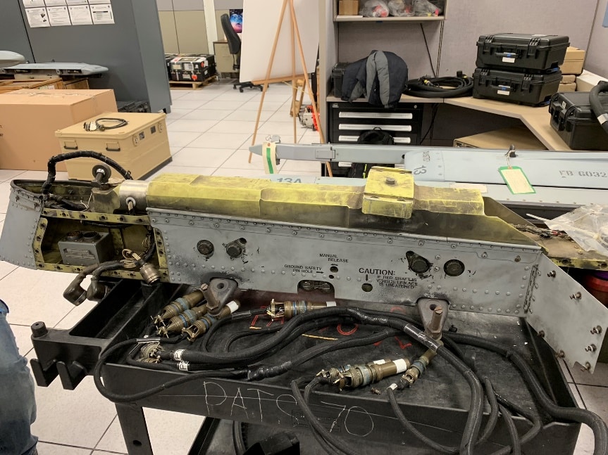

A-10 Weapon Station / Pylon #6
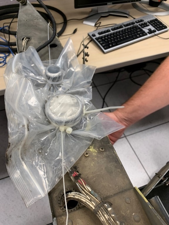

A-10 Weapon Station / Pylon #6 Fuel Tank Plumbing
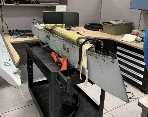

A-10 Weapon Station / Pylon #6
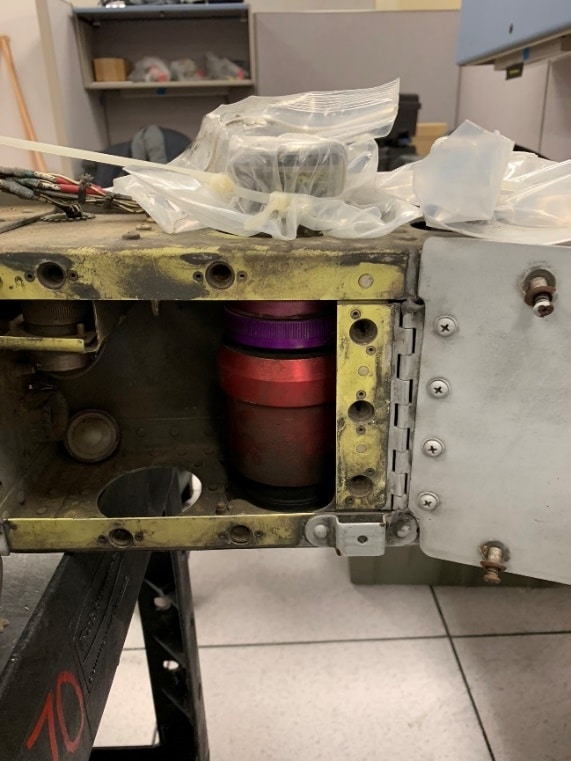

A-10 Weapon Station / Pylon #6 Fuel Tank Plumbing
Portable IFD Test #1
Developmental PATS-70 Cable Set for A-10 Pylon #6
- Automap Completed
- Continuity Test – experienced ohmic variances due to wrap-arounds touching that caused grounding issues – passed Continuity
- Intermittence Test
- Intermittence located on J1-016 – 41 events
- Intermittence located on J1-034 – 67 events
- Intermittence located on J1-035 – 63 events
- Intermittence located on J1-036 – 57 events
- Intermittence located on J1-048 – 58 events
- Intermittence located on J2-043 – 40 events
- Intermittence located on J1-001 – 4 events
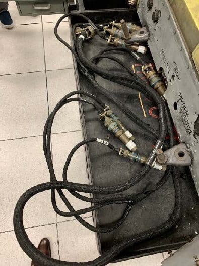

A-10 Weapon Station / Pylon #6 Developmental Cable Set
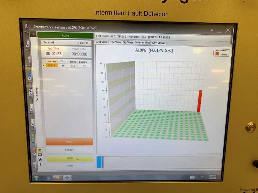

A-10 Weapon Station / Pylon #6 Intermittence
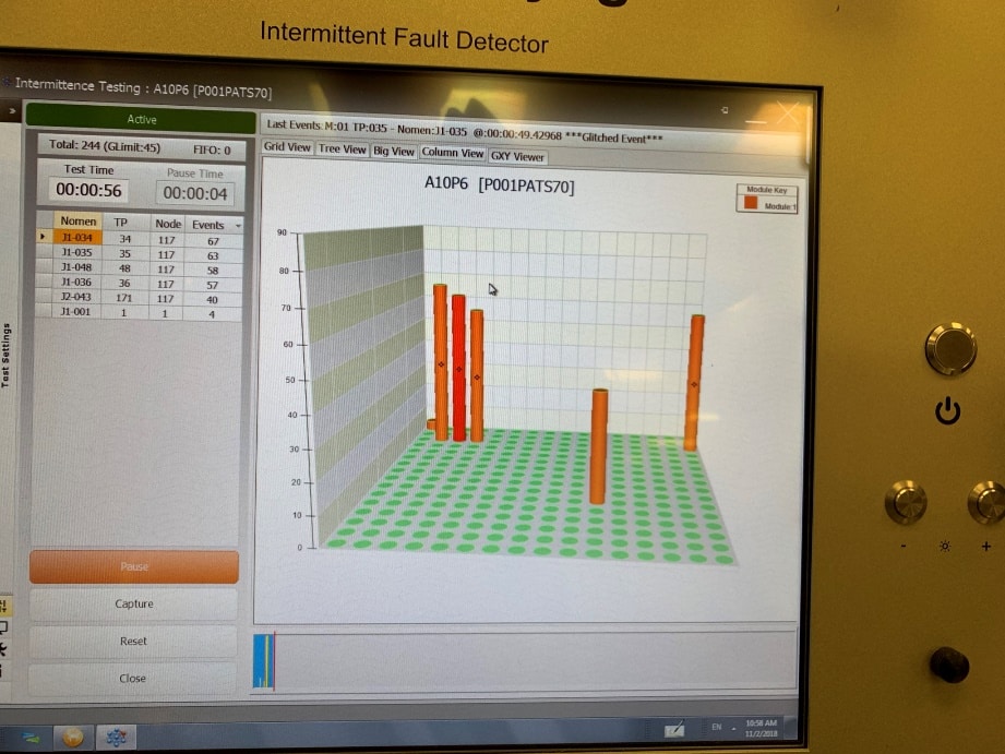

A-10 Weapon Station / Pylon #6 Cable Set Intermittence
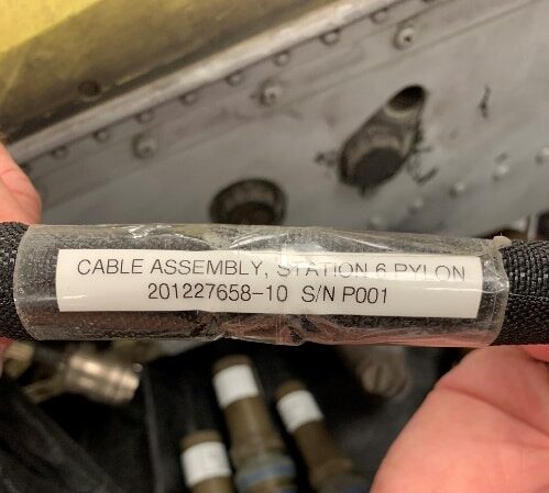

Developmental PATS-70 Cable Set
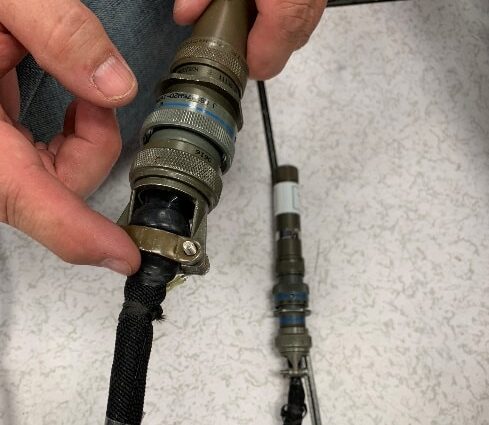

A-10 Weapon Station / Pylon #6 Intermittence Root Cause Location
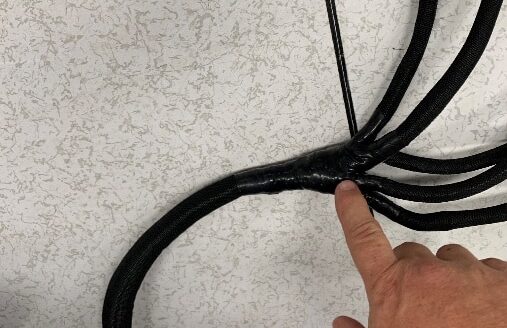

A-10 Weapon Station / Pylon #6 Cable Set Intermittence Root Cause Location
Due to extreme Intermittence in the Pylon #6 Development Cable, it was decided to try an additional PATS-70 pylon cable. A-10 Pylon #2 & #10 Developmental Cable was selected. Ultimately this cable was unable to be used due to the 187-pin cannon plug connectors.
***Program director would like CTMA project for training and testing on 187-pin cannon plug patch cable build and testing with multiple cable sets with this type of connector
Portable IFD Test #2
Finished Pylon #6 testing with Intermittent Faults annotated in PATS-70 cable
- Automap Completed
- Continuity Passed
- Intermittence Test
- Intermittence located on J2-013 – 51 events
- Intermittence located on J2-016 – 29 events
- Intermittence located on J1-016 – 15 events
- Intermittence located on J1-028 – 3 events
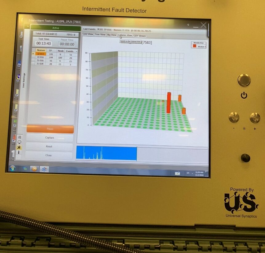

A-10 Weapon Station / Pylon #6 Intermittence
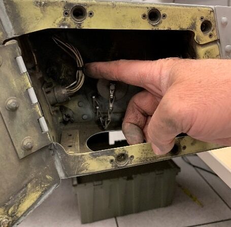

A-10 Pylon #6 Intermittence Root Cause Location
